
The problem this solves
You want one honest number in Home Assistant: how much power this appliance is actually pulling, right
now, and how many kilowatt-hours it burns over a month. The usual DIY answer is a PZEM-004T on a UART — which
means a spare hardware serial (or SoftwareSerial and its timing gremlins under WiFi) and a UART your ESP32
would rather use for something else — and no clean way to add a second circuit when you want one.
There is a shorter path. An rbAmp Basic module talks I²C — two signal wires — and ships as a native ESPHome component. You clamp a CT around one conductor, paste about a dozen lines of YAML, and Home Assistant adopts a device with real voltage, current, power and cumulative energy — without tying up a serial port. This walk-through goes from an unopened box to a live tile in the Energy Dashboard in roughly fifteen minutes. And when you later want a second circuit, you add another small module on the same two wires — not another ESP32.
What you'll have in 15 minutes
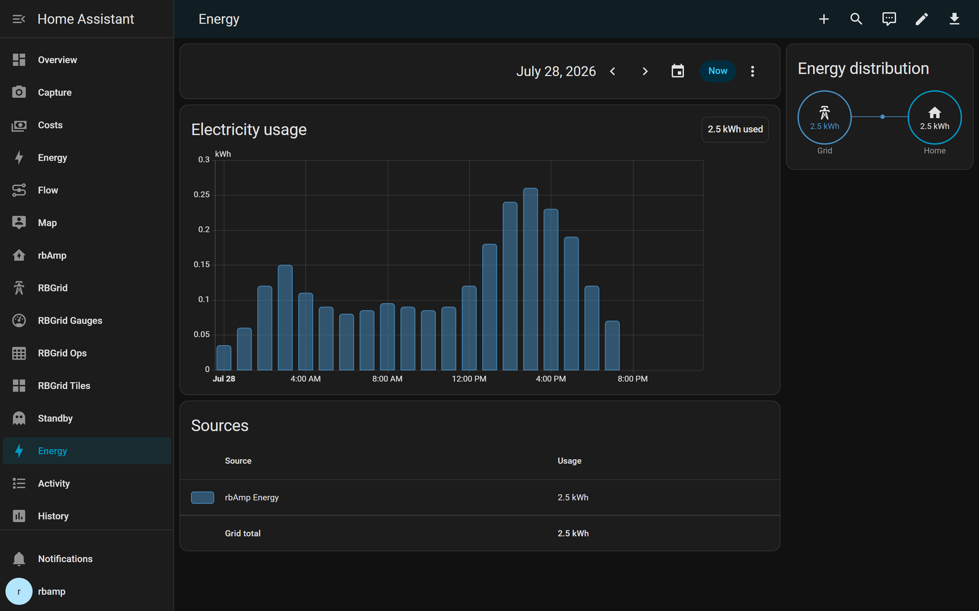 Per-appliance consumption in the HA Energy Dashboard, straight from an rbAmp module over ESPHome.
Why this beats a PZEM
The fifteen-minute setup is nice, but a handful of architectural differences are the real reason to build it this way — and they get more valuable the longer the module runs and the more circuits you add.
- Period windows that close atomically. Beyond the lifetime total, rbAmp can close one measurement window and open the next — per second, per hour, per day, a demand-tariff period — atomically, in a single I²C write. On receipt the module freezes that period's accumulators and starts the next in the same wire moment: no read-loop, no gap. To get the same windowed energy out of a PZEM you'd have to read and zero its accumulator over the UART every interval — CPU and serial time on a link that's already fighting the ESP's WiFi, with the sliver between the read and the reset landing in neither window. Hardware latch versus software workaround. (Broadcast to many modules at once, that same latch keeps a whole panel in sync — the next project in this series.)
- Energy is measured on the device, not guessed in Home Assistant. The rbAmp module does the power measurement and hands the ESP a coherent average-power figure each period; the ESPHome component integrates that into watt-hours and checkpoints them to NVS, so HA receives an already-integrated total. That keeps you out of the single biggest source of bad energy data in HA — letting it integrate power into energy with a Riemann sum between samples, the thing behind the −200 kWh spikes and 10×-too-high days you see all over the forums.
- The module does the hard part — so your host can be cheap. All the sampling, true-RMS, phase correction and calibration run on the rbAmp's own processor; the ESP just reads finished numbers over I²C. A modest host is plenty — an ESP8266 or an ESP32-C2/C3 has ample headroom — leaving your bigger boards for heavier jobs.
- It's a bus, not a point-to-point wire. I²C means several rbAmp modules share the same two signal wires — and modules come in 1-, 2- and 3-channel variants today (with 5- and 7-channel modules on the roadmap), so one module can meter several circuits from a single install point. One ESP32 can read a whole panel — mains, water heater, AC, EV, lighting — and when the modules run off one master they can be latched on the same instant so their sub-totals add up to the feed. A PZEM is one device per UART; you run out of serial ports (and patience) after two. Adding a circuit here costs a small module on the bus, not another microcontroller. (That's the next project in this series.)
Bill of materials
| Item | Why | Price | Where |
|---|---|---|---|
| rbAmp Basic Wattmeter module (V + I, 1 channel) | the meter — reads voltage, current, power, energy | see product page | Basic Wattmeter module |
| SCT-013 current transformer (30 A recommended) | split-core clamp around the conductor | see product page | SCT-013 CT |
| Any ESP32 dev board | Wi-Fi host that talks to Home Assistant | you likely own one | — |
| 4 jumper wires (F–F) | the I²C bus: SDA, SCL, 3V3, GND | — | — |
Which CT? Match the SCT-013 rating to what you're measuring — and note single loads are smaller than they look: a room air-conditioner pulls only ~2–3 A, an electric kettle up to ~10 A. A 5 A or 10 A clamp resolves those finely; 30 A covers a busy wall circuit; 50 A a whole apartment feed. (Sizing a bigger main — roughly 30 A for a floor, 100 A for a house with a workshop and garage — is a whole-panel job: the rbAmp SCT-013 range tops out at 50 A, so larger feeds use the higher-range CT and the whole-panel setup.) For a single appliance, 10–30 A is the safe default. The rbAmp module knows the SCT-013 presets, so calibration is a one-time config value (
ct_model:, below) — no trimming, no burden-resistor math. See CT / sensor selection. (Prefer zero setup? A bundled module + CT kit arrives with the model already set — plug and play.)
Safety first — read this before you touch a panel
⚠️ Working near mains voltage is dangerous. A split-core CT clamps around the outside of an insulated conductor — you never cut, strip, or splice a live wire to install it. If the conductor you want to measure lives inside an electrical panel, have a qualified electrician open and close the panel. The low-voltage side (ESP32, I²C, the CT's 3.5 mm jack) is safe to handle; the conductor the CT hugs is not.
Wire it (about 2 minutes)
Four jumpers between the ESP32 and the rbAmp Basic module:
| ESP32 pin | rbAmp module pin |
|---|---|
3V3 |
3V3 |
GND |
GND |
GPIO21 (SDA) |
SDA |
GPIO22 (SCL) |
SCL |
Then clamp the split-core CT around one insulated conductor of the appliance you want to measure — the line or the neutral, pick one, not both — and plug it into the module's 3.5 mm jack. The module does the rest.
On an ESP32-S3 use
GPIO8(SDA) /GPIO9(SCL); on an ESP32-C3 useGPIO4/GPIO5. Match thei2c:block in the YAML below to your board.
[wiring diagram — media slot: ESP32-DevKitC ↔ rbAmp Basic module, 4 wires, CT clamped on a conductor]
Flash the ESP32 with ESPHome
The whole thing is one file — about a dozen substantive lines. Copy it, edit your Wi-Fi credentials, done.
esphome:
  name: rbamp-energy
esp32:
  board: esp32dev
  framework:
    type: arduino
wifi:
  ssid: !secret wifi_ssid
  password: !secret wifi_password
api:
ota:
  - platform: esphome
logger:
# I²C bus to the rbAmp module. GPIO21/22 are the default pins on a classic ESP32-DevKitC.
i2c:
  sda: GPIO21
  scl: GPIO22
  frequency: 50kHz   # ESP-IDF i2c_master driver + the module's I²C recovery window interact at
                     # 100 kHz → intermittent read NACKs on ESP32. 50 kHz is the robust setting.
                     # STM32 / RP2040 / Linux-SBC masters run this module at 100 kHz fine.
# Pull the rbAmp component from GitHub, pinned to the v1.3.0 release.
external_components:
  - source: github://rb-amp/[email protected]
    components: [rbamp]
# The module itself — 0x50 is the factory-default I²C address.
rbamp:
  id: meter
  address: 0x50
  update_interval: 60s
  # One-time CT setup for the SCT-013 module: tell it which clamp is fitted. This pins the
  # 30 A SCT-013 preset and is written ONCE to the module's flash (idempotent — safe to leave
  # in the config; it only re-writes when the value changes). Match it to YOUR clamp:
  # SCT_013_005 / _010 / _020 / _030 / _050.
  # (Bought a bundled module + CT kit? It is pre-set at the factory — omit this line.)
  ct_model: SCT_013_030
# Voltage · current · active power · cumulative energy → Home Assistant entities.
# The energy sensor is auto-tagged device_class=energy + state_class=total_increasing,
# and its Wh counter is checkpointed to the ESP's NVS on every publish — so it survives
# reboots and power cycles instead of restarting from zero.
sensor:
  - platform: rbamp
    rbamp_id: meter
    voltage:
      name: "rbAmp Voltage"
    current:
      name: "rbAmp Current"
    power:
      name: "rbAmp Power"
    energy:
      name: "rbAmp Energy"
The one line people forget:
ct_model. An SCT-013 module ships blank — it has to be told which clamp you fitted, or its readings are scaled wrong. Settingct_model: SCT_013_030does that once; the module stores it in its own flash and never needs it again (the line is idempotent, so leaving it in the config is harmless). Change the clamp, change the value. If you bought a bundled module + CT kit, the model is pre-set at the factory and you can drop the line entirely — plug and play.
Steps:
- Install the ESPHome CLI (skip if you already run it) — or use the ESPHome add-on inside Home
Assistant; the same YAML applies:
bash pip install esphome - Put your Wi-Fi credentials in
secrets.yamlnext to the config, so they never land in a Git repo by accident:yaml wifi_ssid: "YOUR_SSID" wifi_password: "YOUR_PASSWORD" - First flash over USB (replace
/dev/ttyUSB0with your port —COM3/COM4on Windows):bash esphome run rbamp-basic-ui1.yaml --device /dev/ttyUSB0ESPHome downloads the rbAmp component, compiles, uploads, and streams the boot log. You should see an I²C scan list address0x50, thenrbAmp v1.3.0 initialisedand periodic sensor publishes.
From then on, updates go over the air — no need to unplug anything again:
esphome run rbamp-basic-ui1.yamlHow often should it poll? (
update_interval) The config uses60s, which is right for the Energy Dashboard. You can go faster or slower: the minimum accepted is1s(anything shorter is rejected — the module only refreshes its samples ~5×/second anyway, so sub-second polling just spams the bus), and300s(5 min) is a comfortable ceiling for a quiet, low-traffic sensor. Don't exceed3600s(1 hour) — the Energy Dashboard needs at least one update per hour to draw clean hourly bars. Want a live, twitchy power reading instead? Drop to2s— see Beyond the dashboard below.
See it in Home Assistant
Home Assistant discovers ESPHome devices automatically over mDNS.
-
Open Settings → Devices & Services. A banner appears: "ESPHome — Discovered — rbamp-energy." Click Configure, confirm the encryption-key prompt (leave it blank if you didn't set
api:encryption), and the device is adopted. -
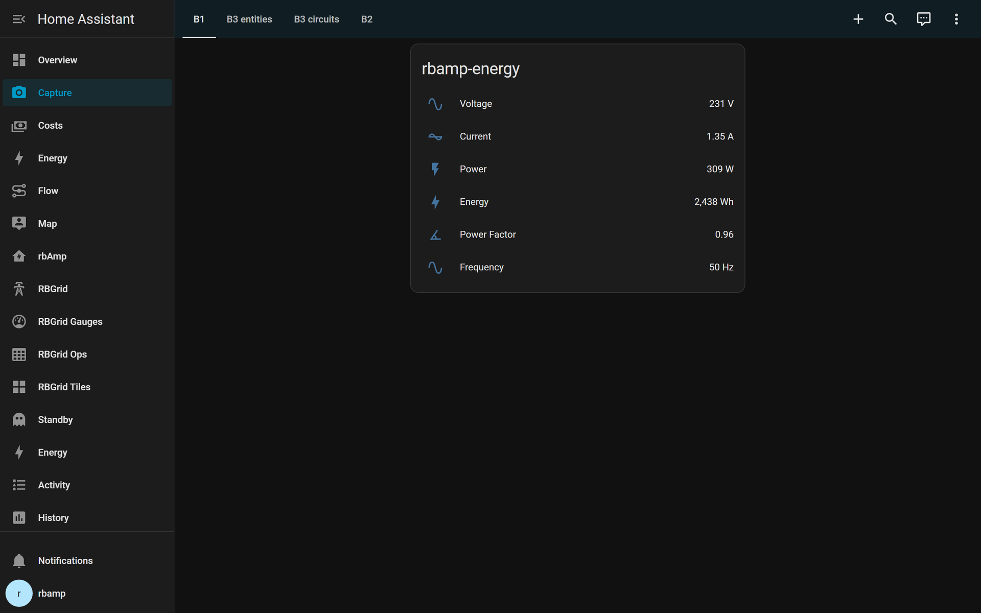
Open the new rbamp-energy device — four entities are waiting:
| Entity | Unit | HA device_class |
Notes |
|---|---|---|---|
sensor.rbamp_voltage |
V | voltage |
RMS mains voltage |
sensor.rbamp_current |
A | current |
RMS current through the CT |
sensor.rbamp_power |
W | power |
Active power (P) |
sensor.rbamp_energy |
Wh | energy |
Cumulative — never resets |
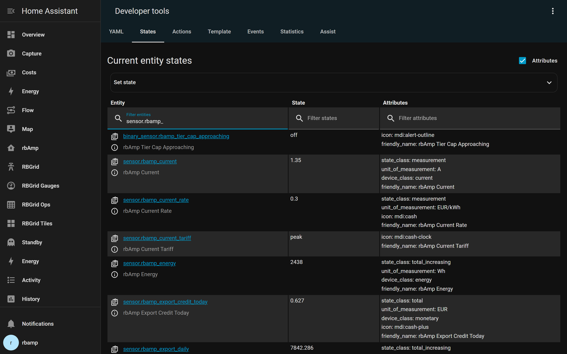
The energy entity already carries state_class: total_increasing, and its counter is persisted to the
ESP's NVS on every publish. Pull the plug, plug it back in — the Wh value continues from where it stopped.
That's exactly what the Energy Dashboard wants.
- Nothing to configure per sensor — the component ships every
device_class,state_classand unit at the platform level, so HA picks them up on discovery.
Add it to the Energy Dashboard
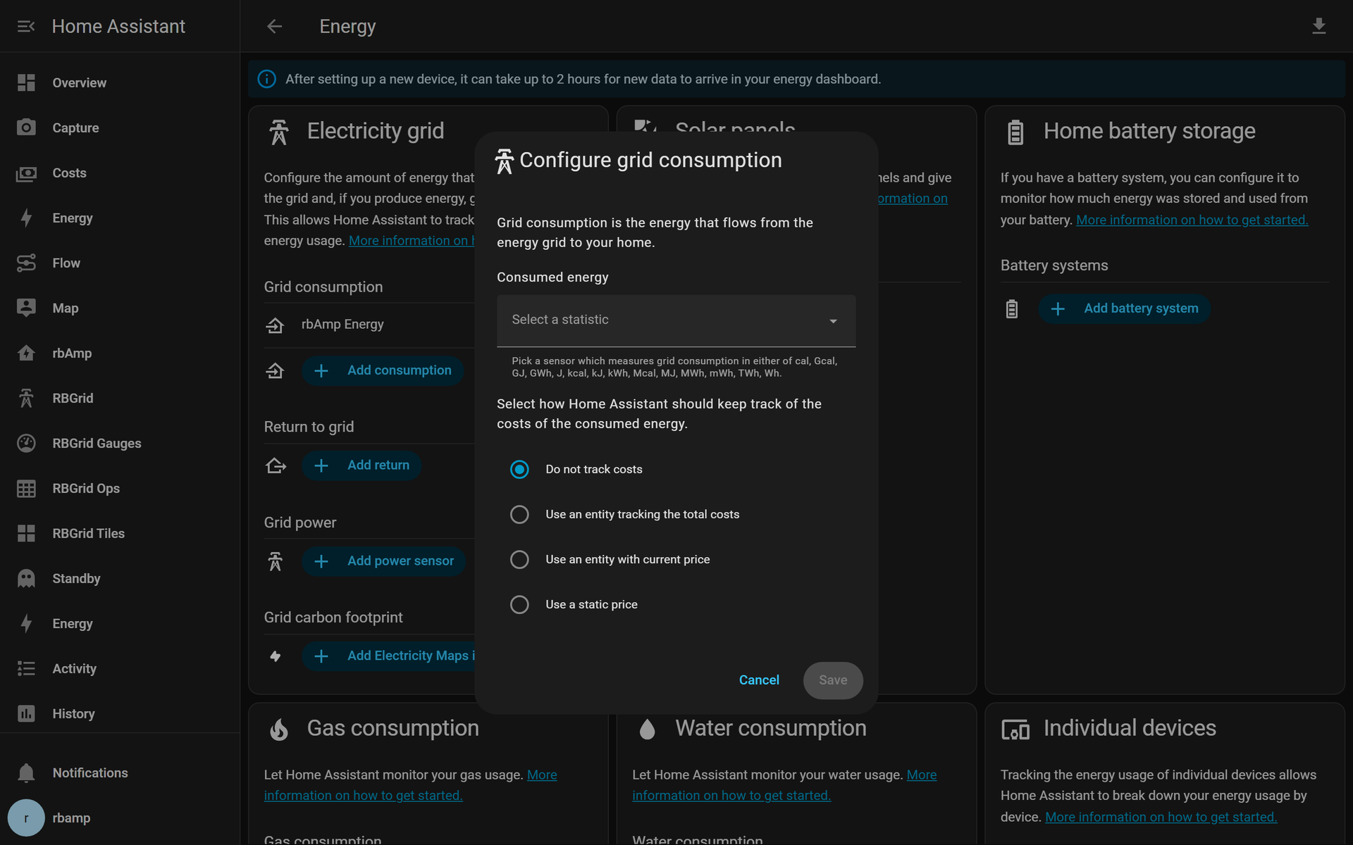
- Open Settings → Dashboards → Energy (or Settings → Energy on newer HA).
- Under Individual devices, click Add device and pick
sensor.rbamp_energy. Home Assistant filters the list todevice_class: energy+state_class: total_increasingentities — the rbAmp energy sensor matches both, so it shows up immediately, no extra flags. - Save. The dashboard needs about an hour to draw its first readable bar; per-hour and per-day totals build from there.
Basic vs Standard. A Basic module measures consumption — power flowing into the appliance. It does not separate import from export, so it belongs in the Energy Dashboard's device / consumption slots, not "Return to grid." For bidirectional grid metering (a solar inverter feed-in, battery export) you want a Standard-series module with its isolated hardware voltage sense — see the tiers overview. Basic is monitoring-grade and calibrated, but it is not a certified revenue meter.
Beyond the dashboard: real-time metering
The Energy Dashboard wants slow, cumulative watt-hours — but the module measures a lot more, and it refreshes
internally about five times a second. If you want a live power gauge, a voltage readout, or power-factor
for automations, add the extra sensors and poll faster. Drop update_interval to 2s (twitchy, you'll see a
kettle switch on within a second) or 5s (smooth trend), and expose the full set:
rbamp:
  id: meter
  address: 0x50
  update_interval: 2s     # live real-time — override the 60s Energy-Dashboard default
  ct_model: SCT_013_030
sensor:
  - platform: rbamp
    rbamp_id: meter
    voltage:        { name: "rbAmp Voltage" }
    current:        { name: "rbAmp Current" }
    power:          { name: "rbAmp Active Power" }
    power_factor:   { name: "rbAmp Power Factor" }
    apparent_power: { name: "rbAmp Apparent Power" }
    reactive_power: { name: "rbAmp Reactive Power" }
    frequency:      { name: "rbAmp Frequency" }
    energy:         { name: "rbAmp Energy" }
Now you can build a live power card, alert on a brownout, or watch power-factor sag when a motor starts. Two things to know so your automations behave:
- Frequency reads 0 during an outage (the detector needs a live waveform), so guard any "frequency
dropped" automation against
0/unavailable. - Power factor is briefly
unavailableat no load — with no meaningful current there's no phase to compute. Let automations tolerateunavailablefor the first couple of seconds after boot.
(Import/export — separate grid consumption from solar feed-in — needs a Standard module with a bidirectional voltage sense; it isn't a Basic capability, so it's left out here.)
Slice it by tariff (peak vs off-peak)
On a time-of-use plan you'll want to know how many watt-hours landed in the peak window versus off-peak —
without buying anything extra. Home Assistant does this natively: point its built-in utility_meter at the
one rbAmp energy entity and let HA split it into tariff sub-meters. This goes in HA's configuration.yaml, not
the ESPHome YAML:
utility_meter:
  rbamp_energy_tou:
    source: sensor.rbamp_energy
    tariffs: [peak, off_peak]
    cycle: monthly
Then add a small automation that flips the active tariff at your window boundaries — e.g. peak at 07:00 and
off_peak at 22:00 — by calling utility_meter.select_tariff. HA keeps a separate running total for each
tariff on top of the single Wh counter the module provides. One meter, as many tariff buckets as your plan
needs — and it works with any ESPHome energy sensor.
What's next
You now have one honest circuit in Home Assistant. Where this goes from here:
- The whole panel on one ESP32. Put a multi-channel module (or several single-channel modules) on the same two I²C wires — mains, stove, water heater, AC, lights — one ESP32, one YAML. Adding a branch costs a small module, not another microcontroller. (Next in this series.)
- Migrating from a PZEM? Keep your Home Assistant history, free up the UART, and gain reboot-proof watt-hours. (Next in this series.)
- Hunt the vampires. Once every circuit is metered, the standby floor — the ~35 W that never sleeps — becomes visible and payable. (Next in this series.)
For the theory under all of this — how a CT actually turns a magnetic field into kilowatt-hours — see the ESPHome quickstart and the full Home Assistant integration guide.
Related guides & FAQ
- The whole panel on one ESP32 — real per-circuit energy across the house.
- Migrating from a PZEM-004T — keep your Home Assistant history.
- The rbAmp UI series — 1 to 7 metering channels on one I²C bus.
- rbAmp vs PZEM-004T — which AC energy monitor for ESP32 & Home Assistant?
- rbAmp vs Shelly EM — modular DIY vs a turnkey certified meter.
- rbAmp FAQ — accuracy, isolation, reboot-proof energy, and more.
[newsletter / early-adopter subscribe block — deploy session inserts the site's standard subscribe snippet]