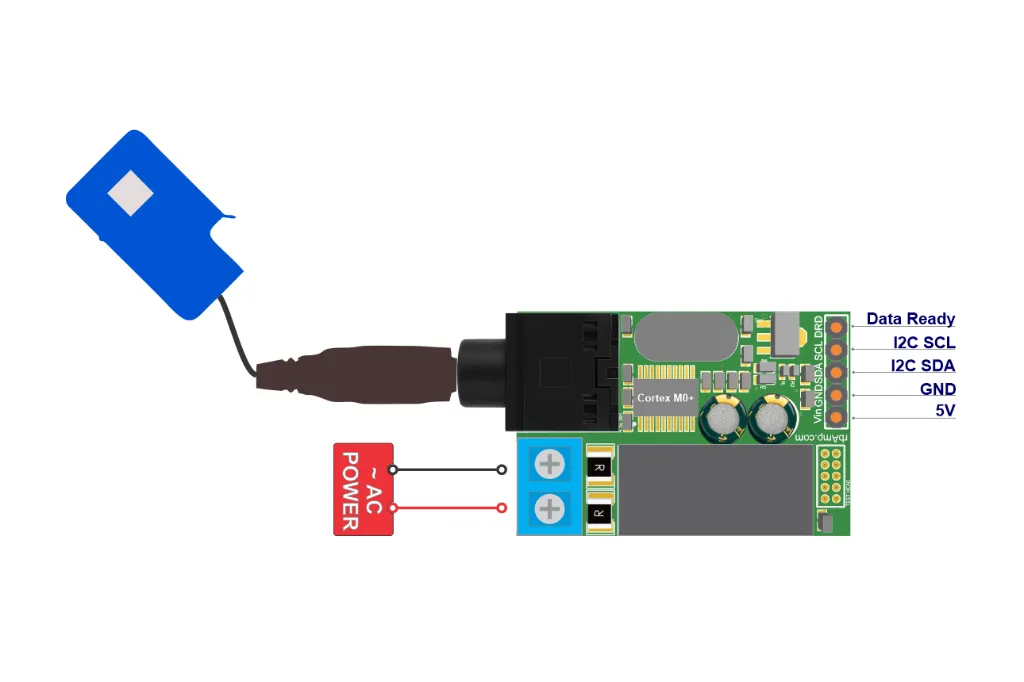
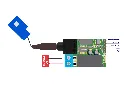
Basic AC Power Wattmeter for a precision through-core CT — single or dual-load configuration on a clean I²C bus, with an isolated voltage front-end. Pairs with a through-core CT TA sensor on a wire (one per current channel) — buy the module alone, or get the Module + Sensor bundle. More accurate than SCT-013 — 40–60 mA noise floor (3–5× better), loads visible from 50 W. Drop-in PZEM / JSY / HLW replacement that integrates natively with Home Assistant via ESPHome, with master-driven atomic period latch for drift-free tariff-grade Wh accounting.
- You want a precision through-core CT — pick the matching sensor, or grab the Module + Sensor bundle
- SCT-013 noise hides your fridge or water heater in the baseline (40–60 mA noise floor instead of 150–200 mA)
- Your tariff went hourly and your UART meter loses energy in the read-reset gap
- You need 2 loads measured on one module with a shared voltage reference
- Your PZEM / JSY works, but you need a second one and your ESP32 UARTs are taken
Choose your channel count
| Variant | Voltage input | Current channels | What it measures | Energy (Wh) |
|---|---|---|---|---|
| UI1 | 1 (line-to-neutral) | 1 | U, I, P, PF, frequency, energy — one load | ✅ |
| UI2 | 1 (shared) | 2 | Shared U + per-channel I, P, PF on two loads | ✅ |
Basic CT Wired tops out at UI2 (2 current channels). For more channels per module, see the Standard line (up to UI8). The matching through-core CT is sold separately or as a Module + Sensor bundle.
Five lines of YAML — module in Home Assistant
rbamp:
  - id: rbamp_main
    address: 0x60
    data_ready_pin: GPIO4

sensor:
  - platform: rbamp
    rbamp_id: rbamp_main
What you get
Precision through-core CT measurement chain
Built for through-core CT TA sensors (no air gap) — tighter accuracy than clamp-on SCT-013. Total accuracy = module + sensor: the module adds ~0.5%, the CT sensor 0.3–1%. Noise floor 40–60 mA — 3–5× better than SCT-013, enough to see loads from 50 W upward. Factory pre-calibrated against a reference instrument, with per-unit coefficients in persistent memory.
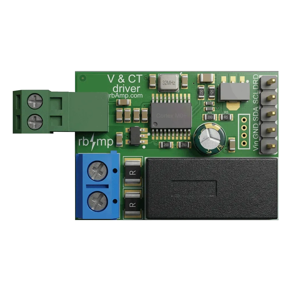
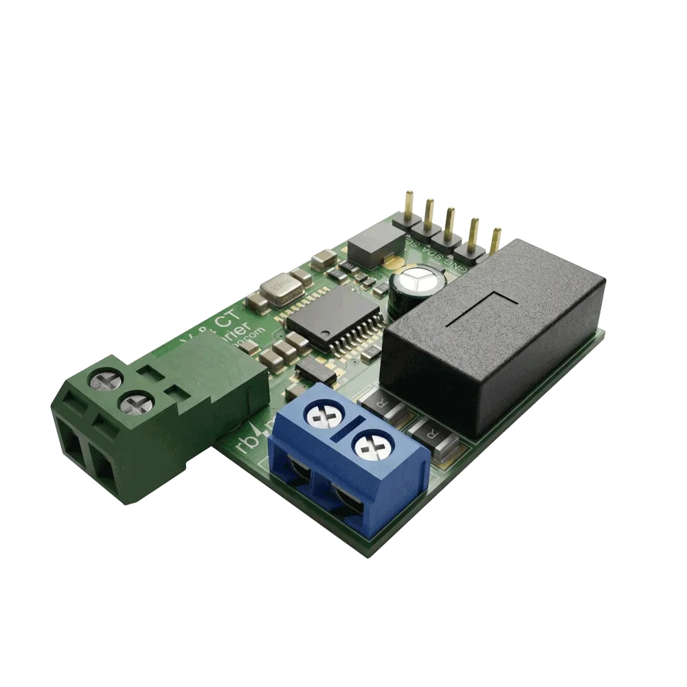
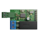
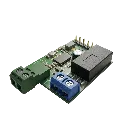
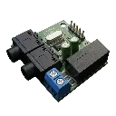
Plug-in screw terminals — wired sensor
The CT TA sensor connects through plug-in (pluggable) screw terminals: the terminal block unplugs from the board and the secondary wire is secured under a screw. No soldering. The voltage input uses a separate screw terminal (line + neutral).
Atomic period latch
Master sends CMD_LATCH_PERIOD; the module returns period_avg_P_W (float32 average active power for the period). Master multiplies by wall-clock dt to get Wh. No read-reset gap. Drift-free tariff metering at hourly cadence and beyond. The module returns averaged power for the period — the Wh = P × dt / 3600 computation runs master-side.
5 kHz hardware sampling
True-RMS calculation over 1000 samples per 200 ms window on-module via DMA. Your ESP32 reads pre-computed values, not raw ADC samples. Frees the host MCU for application logic.
Native ESPHome integration
Auto-discovery via the rbamp-esphome external_component. Roughly 5 lines of YAML for a single module. All sensors surface as native Home Assistant entities — U_rms, I_rms, P_active, PF, frequency, energy accumulator.
CT TA advantages over SCT-013
| Parameter | CT TA (through-core) | SCT-013 (clamp) |
|---|---|---|
| Sensor accuracy | 0.3–1% | 1–3% |
| Noise floor | 40–60 mA | 150–200 mA |
| Visibility of small loads | from 50 W | from 200 W |
| Air-gap effect | none | 1–2% extra error |
| Batch-to-batch stability | high | medium |
| Installation | requires power-down | non-invasive |
Total accuracy = module (~0.5%) + sensor. Figures above are the sensor error. Pick a tighter sensor for tighter results.
What's in the box
- rbAmp Basic CT Wired Wattmeter module (PCB)
- Plug-in screw terminal blocks for tool-free sensor connection
- Screw terminals for the voltage input (one set, line + neutral)
- Quick reference card with link to documentation
Module only — the CT sensor is not included. Buy the matching through-core CT TA separately, or get the Module + Sensor bundle (module + 1–2 CT sensors, depending on variant). The module pairs with any current-output CT in range; the bundle ships the factory-matched sensor.
Real-time data (refreshed every 200 ms)
| Register | Description |
|---|---|
U_rms |
RMS line voltage (V) |
I_rms[ch] |
RMS current per channel (A) — 1 or 2 channels depending on variant |
P_active |
Active power per channel (W, signed — direction-flow diagnostic) |
Q_reactive |
Reactive power (var, signed: + inductive, − capacitive — load-type diagnostic, NOT counted in energy) |
PF |
Power factor (signed: leading / lagging) |
Frequency |
Line frequency (Hz) |
period_avg_P_W |
Atomic period latch — average active power for the current period (see Atomic period latch section below for master-side Wh computation) |
Signed P_active. In live mode, P_active is signed: positive = consumption, negative = export. This is diagnostic (detect reversed CT, catch unexpected export, verify sensor orientation). For billing-class energy the Basic line counts consumption only (unidirectional firmware clamp — export samples are dropped before summing). For bidirectional accounting (solar feed-in) — rbAmp Standard.
Atomic period latch (UI configurations)
| Item | Description |
|---|---|
CMD_LATCH_PERIOD |
Master-issued command. Atomic snapshot: closes the current period + opens the next, in one I²C transaction. |
period_avg_P_W |
Float32 register. Average active power for the closed period — master reads this after each LATCH. |
| Atomicity guarantee | Every 200 ms power sample lands in either the previous or the next period — never in a read-reset gap. Drift-free Wh accounting against utility meter. |
| Mode 1 — continuous | One LATCH per period boundary. Optimal for tariff billing: 1-min logs, 15-min peak demand, hourly tariff zones, daily totals. Minimum I²C transactions. |
| Mode 2 — event-based | Two LATCHes for arbitrary start / end. Clean period for event-driven accounting: contactor close / open, EV charging session start / stop. |
| Master computation | Wh = period_avg_P_W × dt / 3600 where dt = master's wall-clock interval between LATCHes (in seconds). |
| Multi-channel (UI2) | Single CMD_LATCH_PERIOD atomically snapshots both channels simultaneously. Per-channel period_avg_P_W[ch] registers — read each after one LATCH, compute per-channel Wh against the same wall-clock dt. |
Compatibility
- ESPHome — native
external_componentwith auto-discovery (rbamp-esphome on GitHub) - Home Assistant — via ESPHome, all sensors as native HA entities
- Arduino / PlatformIO — high-level library (rbamp-arduino on GitHub)
- Raspberry Pi — Python via I²C (rbamp-examples on GitHub)
- Tasmota — Berry driver
- Any I²C master — documented register map at /docs/modules-basic-standard-api-reference
Specifications
| Spec | Value |
|---|---|
| Supply voltage (VCC) | 5 V DC (on-board 3.3 V regulator) — do NOT drive VCC with 3.3 V |
| I²C / DataReady logic level | 3.3 V (ESP32 / Raspberry Pi GPIO direct, no level shifter) |
| Current draw | <20 mA typical |
| MCU | ARM Cortex-M0+ |
| Interface | I²C, 100 kHz / 400 kHz |
| I²C address | 0x60 default, programmable |
| DataReady pin | Open-drain, idle HIGH, ~10 µs LOW pulse every 200 ms — falling-edge interrupt |
| AC voltage range | 90–280 VAC, 50/60 Hz |
| AC current range | 0.25–100 A (depends on the CT model) |
| Accuracy (current) | module ~0.5% + sensor (CT) 0.3–1% — total = module + sensor |
| U_rms accuracy | ±2–3% |
| Power accuracy (above 20 W) | ±2–3% |
| Current noise floor | ~40–60 mA |
| Sampling rate | 5 kHz per channel (5,000 samples per second) |
| Real-time integration window | 200 ms |
| ADC resolution | 12-bit |
| Current sensor type | Through-core CT TA, current output (mA), on a wire — sold separately / bundle |
| Sensor connection | Plug-in screw terminals (no soldering) |
| Voltage front-end | Isolated |
| AC mains isolation | Full galvanic (isolated voltage front-end + toroidal CT + I²C bus) |
| AFE | Precision burden resistor (Vishay 0.1%) + unity-gain bias buffer + AC-coupling (protects CT from DC saturation) |
| Connector for voltage input | Screw terminals (line + neutral) |
Multiple modules on one bus
Each module ships with 4.7 kΩ pull-ups on SDA and SCL. On the first module leave the pull-up jumpers closed; on every additional module cut the marked jumpers (a few seconds with a knife or soldering iron) so parallel pull-ups don't overload the master. Up to 8 modules per bus at ~30 cm runs. Longer runs → see the Standard line.
Installation safety
⚠️ Through-core CT install requires powering down the wiring — the primary conductor must pass through the toroidal sensor, which means temporarily freeing or disconnecting the wire. This is a one-time install. If you can't power down the circuit, use rbAmp Basic SCT-013 with its non-invasive clamp. All work must follow local electrical codes; for panel-level work, a qualified electrician is strongly recommended.
⚠️ The module ships as a bare PCB. The Basic line does not include enclosures — for DIN-rail housings or panel boxes, use third-party project enclosures.
This module is not certified for revenue metering (utility-grade billing). For commercial accounting, use a certified meter alongside rbAmp for diagnostic / per-circuit detail.
Warranty and support
- 12-month warranty on electrical defects
- GitHub Discussions — public support channel at github.com/rb-amp
- Documentation — Quick Start · API Reference · Migration from PZEM-004T
Upgrade pointer
Only need current channels (no voltage / power / Wh)? Get the CT Wired Ammeter (A-series — same through-core CT, current measurement only, lower cost).
Looking for higher accuracy? rbAmp Standard tier delivers a tighter module (~0.3%), sub-10 mA noise floor, signed power for solar bidirectional, 8 independent atomic-period accumulators, diagnostic alarms, and traceable factory calibration. Drop-in upgrade on the same I²C bus (different address range).