04 · Wiring
This chapter covers the physical wiring of rbAmp to an ESP32: GPIO selection, pull-up rules, multi-module bus, power, the optional DRDY line, and address provisioning.
LV-side pinout
The low-voltage side of the module exposes five signals. All are galvanically isolated from mains — the GND pin is the ESP32 GND, not mains neutral.
| Pin | Signal | Description |
|---|---|---|
VCC |
+4.5..+5.5 V DC | Module power. 5 V nominal; below 4.5 V the ADC may lose accuracy. |
GND |
Common | Shared with the master. Required. |
SDA |
I²C data | 3.3 V logic; 5 V-tolerant. |
SCL |
I²C clock | 3.3 V logic; 5 V-tolerant. |
DRDY |
Data ready (optional) | Open-drain output. A ~10 µs LOW pulse every ~200 ms after the instantaneous registers are updated. |
GPIO selection on ESP32
Any pair of I²C-capable GPIOs will work. The ESP32 peripheral matrix lets I²C be routed to almost any pin. Practical constraints:
- GPIO0 and GPIO2 — boot-strapping pins. A low level on either at power-on blocks boot. Do not use.
- GPIO 6..11 — wired to the internal flash or PSRAM on most ESP32-WROOM modules. Not available.
- GPIO 34..39 — input-only. Not suitable for I²C (bidirectional drive required).
- Do not connect any ESP32 GPIO to a module reset line — the module is reset by an I²C command, no hardware reset pin on the master side is needed.
Recommended defaults that work on most ESP32-DevKitC boards:
| Signal | GPIO | Note |
|---|---|---|
| SDA | GPIO21 | Default in every example YAML |
| SCL | GPIO22 | Default in every example YAML |
| DRDY | GPIO15 | Optional; any input-capable pin works |
If GPIO21/22 are taken, pick any other valid pair and update the i2c: block in YAML.
Single-module wiring
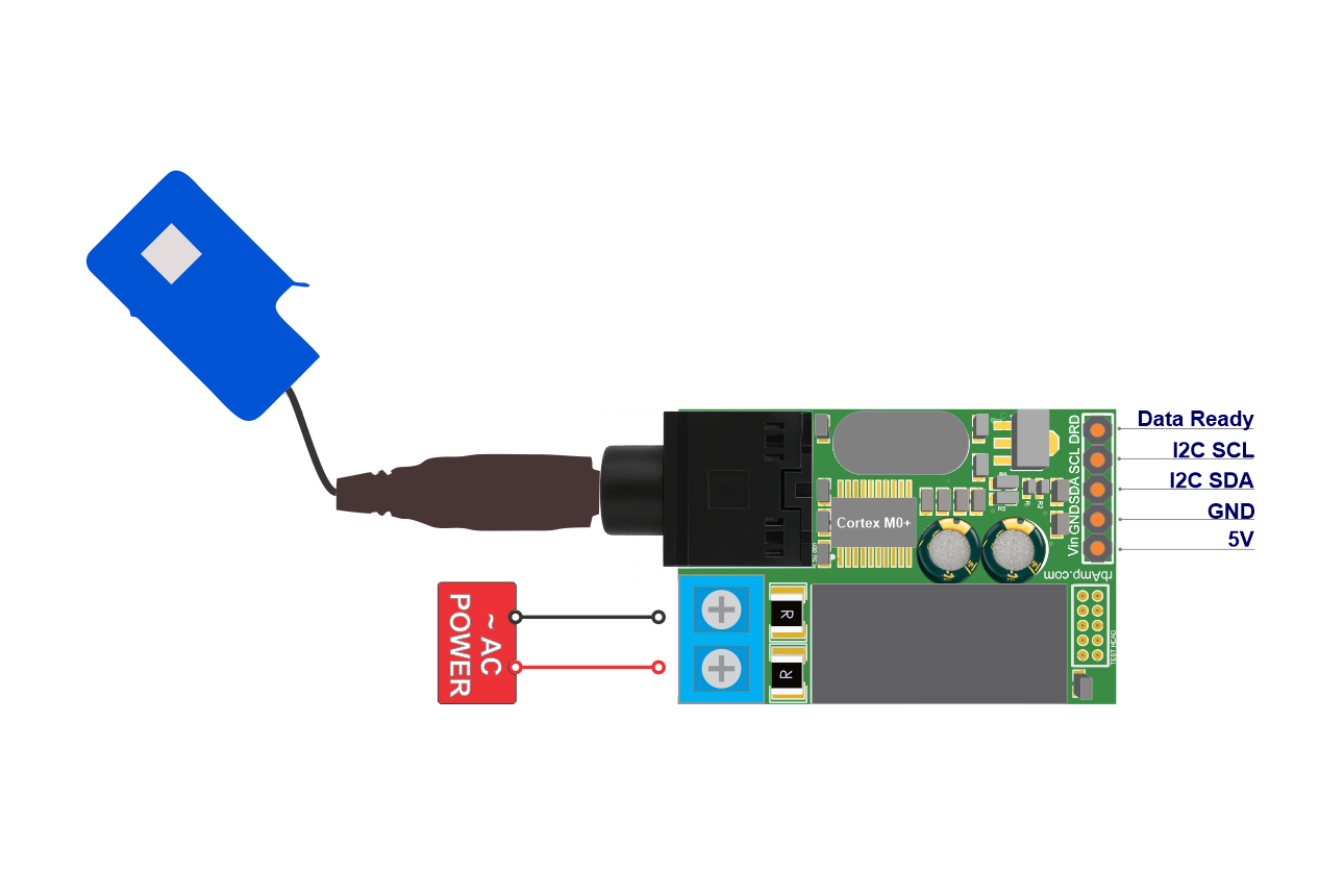
External pull-up resistors are not needed for a single module — the rbAmp PCB carries built-in 4.7 kΩ pull-ups on SDA and SCL to 3.3 V.
Multi-module bus
When two or more modules share a bus (or any other I²C devices with their own pull-ups), their pull-ups combine in parallel. The total resistance drops below the effective minimum, which causes:
- Excessive bus current draw.
- Possible overload of the ESP32 open-drain outputs (typically ≤ 3 mA at 3.3 V).
- Higher capacitive load on a long bus.
The underside of every rbAmp PCB carries solder jumpers labeled Pull-Up. Cutting the trace with a sharp blade disables the built-in 4.7 kΩ pair on that module.
| Modules on bus | Pull-up configuration | Effective R |
|---|---|---|
| 1 | Keep built-ins. No externals. | ~4.7 kΩ |
| 2 | Keep on the first, cut on the second. | ~4.7 kΩ |
| 3 | Cut on all. External pair 2.7..3.3 kΩ at the ESP32. | 2.7..3.3 kΩ |
| 4..6 | Cut on all. External pair 2.2..2.7 kΩ at the ESP32. | 2.2..2.7 kΩ |
| 7..16 | Cut on all. External pair 1.5..2.2 kΩ at the ESP32 + check bus capacitance (see below). | 1.5..2.2 kΩ |
| ESP32 already provides pull-ups | Cut on every module. The ESP32 internal pull-ups (≥50 kΩ) are weak — a long bus still needs external 2.2..4.7 kΩ. | as above |
Selection logic: the effective R_pullup is the parallel combination of every active pull-up. The target range is 1.5..4.7 kΩ (the floor is set by the ESP32 sink current ≤ 3 mA at 3.3 V; the ceiling by the bus RC time constant). Formula: 1/R_eff = N/R_unit. With the built-in 4.7 kΩ pair: 2 modules = 2.35 kΩ, 3 = 1.57 kΩ, 4 = 1.18 kΩ — at 3 modules the result is already too low, so the table cuts every built-in jumper starting at 3 modules and falls back to a single external pair.
Diagnostic check: measure the resistance between SDA and VCC with the power off. The result should be in the 1.5..4.7 kΩ range. Below 1.0 kΩ — too many pull-ups in parallel; above 10 kΩ — no active pull-up (check the jumpers).
Bus capacitance (for ≥7 modules or total wiring length > 50 cm): the I²C spec caps total C_b at ≤ 400 pF. A short bus with 2-3 modules is typically 50..100 pF; a 1 m bus with 10 modules can climb to 300..400 pF. When approaching the limit, drop to frequency: 50kHz (if you were on 100 kHz) or use an active-pullup IC (for example PCA9517).
Bus speed
Set frequency: 50kHz in the ESPHome i2c: block. On ESP-IDF-based masters (which ESPHome always uses) this is the recommended, robust setting:
i2c:
  sda: GPIO21
  scl: GPIO22
  frequency: 50kHz    # recommended on ESP32 — ESP-IDF i2c_master driver interaction, see below
The module periodically NACKs reads from an ESP32 at 100 kHz (~20% of transactions) because of the interaction between the ESP-IDF v5 i2c_master driver timing and the post-STOP recovery window of the module's I²C peripheral (details in libs/spec/SPEC.md Appendix B.5). At 50 kHz the NACK rate drops by about a factor of 5, and the per-byte retry inside the component recovers > 99% of valid reads.
Firmware has hardened the module's I²C recovery window (shipped in v1.1 and v1.3), which shrank the module-side contribution — but 50 kHz remains the recommended setting on ESP-IDF-based masters because the driver-timing interaction persists at 100 kHz. Treat it as the standing recommendation for ESP32, not a temporary workaround awaiting a fix.
Other I²C masters run this module at 100 kHz cleanly: STM32 HAL, RP2040 SDK, Raspberry Pi smbus2 (Linux-kernel I²C), and non-ESP32 Arduino (AVR / STM32duino). Note the axis is the driver, not the board: Arduino on an ESP32 uses the same ESP-IDF i2c_master driver, so it wants 50 kHz too — only non-ESP32 Arduino runs 100 kHz.
Reference schematic — one ESP32 + one rbAmp
rbAmp
                                     +-------------------+
  ESP32                              |   LV side         | Mains side
  -----                              |                   |
  GPIO22 (SCL) ──────────────────── SCL                  |◄[terminal L]── L
  GPIO21 (SDA) ──────────────────── SDA                  |◄[terminal N]── N
  GPIO15 (input) ◄──[10K to 3.3V]── DRDY (open-drain)    |
  3.3V ─────────────────────────── (pull-up reference)   |◄[CT jack]── SCT-013
  5V ──────────────────────────── VCC                    |
  GND ─────────────────────────── GND                    |
                                     +-------------------+
Notes:
- The 10 kΩ resistor on DRDY belongs on the master side (near the GPIO), not on the module side. DRDY is open-drain with no internal pull-up.
- The CT jack must be fully inserted; the clamp must fully enclose a single conductor with the arrow pointing toward the load.
- L/N polarity on the terminals affects the sign of P (see Sensor Selection).
Power
Module power (VCC)
The module requires +4.5..+5.5 V DC. Current draw:
| Mode | Typical |
|---|---|
| Steady-state measurement | ~15 mA |
Flash write (during ct_model: / address provisioning) |
~25 mA peak, ~700 ms |
| Boot warm-up (~250 ms) | ~15 mA |
The 5V pin on the ESP32-DevKitC (usually tied to USB VBUS) can power the module directly — the USB host must supply the combined ESP32 (~200 mA) plus rbAmp (~15 mA peak) = ~215 mA. For installs where the ESP32 is fed from an external 5 V SMPS, connect VCC to the same 5 V rail.
ESP32 brownout
The ESP32 brownout detector trips at about 2.43 V on VDD. When it fires, the I²C bus goes idle while the module keeps measuring on its own (it has independent 5 V power). When the ESP32 recovers, setup() restores the accumulated energy from NVS before the first update(). Home Assistant sees neither a gap nor a reset in the energy graph.
Optional DRDY
The DRDY pin on the module is open-drain. It pulses LOW for ~10 µs every ~200 ms immediately after the instantaneous-register block is refreshed. It does not fire on a period snapshot.
With update_interval: 60s you can omit DRDY — the component checks the status register at the start of every update() and skips the read if the module is not ready. DRDY is only useful when you need sub-second delivery of instantaneous data with minimal latency (interrupt-driven reads).
DRDY wiring
DRDY is open-drain: it pulls LOW but cannot drive HIGH. An external pull-up is required:
rbAmp DRDY  ──────────────────┬── ESP32 GPIO (input)
                                 |
                               [10K]
                                 |
                               3.3V
10 kΩ to 3.3 V. Do not connect DRDY to 5 V, even though SDA/SCL are 5 V-tolerant — DRDY is a separate signal and the absolute maximum on an ESP32 input GPIO is 3.6 V.
Declare the pin in YAML:
rbamp:
  id: meter1
  drdy_pin: GPIO15
Multi-module DRDY
DRDY signals from several modules can be wire-OR'd onto a single ESP32 GPIO (open-drain outputs combine naturally). The shared signal goes LOW when any module refreshes its instantaneous registers. The component uses this only as a hint and does not distinguish which module fired.
If you need separate signals, route each module's DRDY to its own GPIO and declare drdy_pin: separately in each rbamp: block.
Address provisioning on a multi-module bus
All rbAmp modules ship from the factory at address 0x50. Before connecting several modules to one bus, every module needs a unique address.
Serial provisioning:
- Connect only module 1 to the ESP32 (one module on the bus).
- Flash the configuration from
example/address_change.yamlwithaddress: 0x50andnew_address: 0x51. At boot the component detects the mismatch and runs the address-change sequence: write the new address, save to flash (~700 ms), soft reset (~300 ms), verify on the new address. - Confirm success in the ESPHome logs. Update the YAML:
address: 0x51, removenew_address:. - Disconnect module 1. Connect module 2 (still at factory
0x50). - Repeat for
0x52,0x53, and so on. - Once every module has a unique address, connect them all to the bus. Cut the pull-up jumpers on all but one (see the rules above).
Serial provisioning avoids address collisions during the change. On current firmware (v1.3+), writing a new address needs no special mode, jumper, or factory tooling — the component stages the new address, arms the change, and commits it (a two-phase, magic-armed sequence so an address can't change by accident), and the module reboots at its new address.
Multi-module YAML example
i2c:
  sda: GPIO21
  scl: GPIO22
  frequency: 50kHz
  scan: true
rbamp:
  - id: meter_house
    address: 0x50
    update_interval: 60s
  - id: meter_solar
    address: 0x51
    update_interval: 60s
    bidirectional: true
  - id: meter_evcharger
    address: 0x52
    update_interval: 60s
sensor:
  - platform: rbamp
    rbamp_id: meter_house
    voltage: { name: "House Voltage" }
    current: { name: "House Current" }
    power:   { name: "House Power" }
    energy:  { name: "House Energy" }
  - platform: rbamp
    rbamp_id: meter_solar
    voltage: { name: "Solar Voltage", internal: true }
    current: { name: "Solar Current" }
    power:   { name: "Solar Power" }
    energy:  { name: "Solar Energy" }
    energy_exported: { name: "Solar Energy Exported" }
  - platform: rbamp
    rbamp_id: meter_evcharger
    voltage: { name: "EV Charger Voltage", internal: true }
    current: { name: "EV Charger Current" }
    power:   { name: "EV Charger Power" }
    energy:  { name: "EV Charger Energy" }
A fully annotated version with broadcast_latch: forward-compat is in example/multi_module.yaml.
Bus length
I²C is a short-haul protocol. Verified lengths for rbAmp:
| Cable type | Maximum length | Speed |
|---|---|---|
| Standard JST / 4-conductor flat | 0.3 m | 50 kHz |
| Twisted pair (SDA+GND and SCL+GND in separate pairs) | 1 m | 50 kHz |
| Twisted pair + I²C buffer (PCA9515 / TCA9617) | 3 m | 50 kHz |
| Differential bus (PCA9615 / LTC4332) | 100 m | 50 kHz |
For runs longer than 0.3 m, use twisted pair, and route SDA and SCL in separate pairs (for example blue + blue-white for SDA, green + green-white for SCL). If SDA and SCL share a pair, cross-coupling distorts the edges even at 50 kHz.
Address change and factory / service mode
On current firmware (v1.3+), changing a module's I²C address needs no special mode, jumper, or factory tooling — the component stages the new address, arms the change, and commits it (a two-phase, magic-armed sequence so an address can't change by accident), and the module reboots at its new address. This is a normal field operation.
A separate factory/service mode still gates a few manufacturer operations such as factory reset. That mode has nothing to do with addressing; standard production modules ship with it disabled, and it is not needed to change an address.
Configuring the current sensor (
ct_model:/ct_models:) does not require factory/service mode — on firmware v1.2+ the module accepts CT-model writes directly (see Sensor Selection).
What's next
- Quickstart — first boot in 5 minutes
- Examples — full scenarios: UI1 / UI3 / multi-module / address provisioning
- Troubleshooting — symptom-driven diagnostics
Source & issues: rb-amp/rbamp-esphome · this page in the repo: docs/04_hardware.md