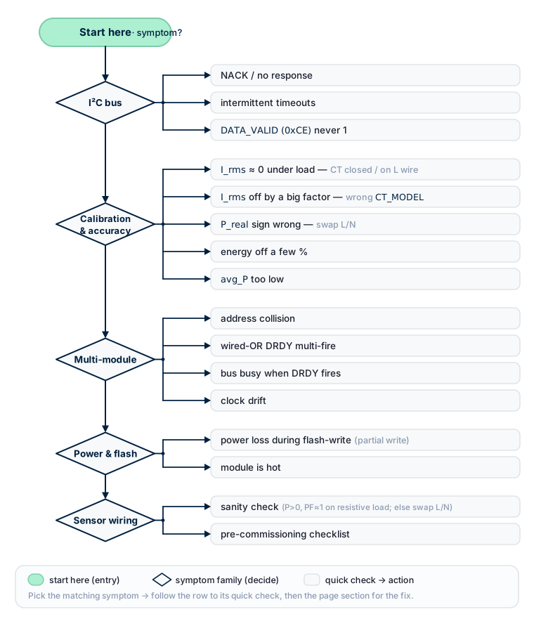
05 · Troubleshooting
This chapter is a quick reference for common problems and their solutions. Each entry follows the structure:
- Symptom — what the user observes
- Causes — why it can happen
- What to check / do — concrete actions
I2C bus
1. NACK / no response from the module
Symptom: Wire.endTransmission() returns non-zero; i2cdetect does not show the address on Linux; rb_read_u8() returns 0xFF.
Causes and checks:
- ❌ Module power is missing or unstable — measure VCC with a multimeter; it must be 5 V ±5%.
- ❌ No common ground — the single most frequent mistake. Master GND and module GND must be tied together.
- ❌ SDA and SCL swapped — verify against the wiring diagram in 01_hardware.md.
- ❌ No pull-ups on the bus — if the built-in pull-ups have been cut on a module and no external ones are installed, the bus is dead. With everything unpowered, measure SDA↔VCC: it must read 1.5–4.7 kΩ.
- ❌ Too many pull-ups in parallel — built-in pull-ups still active on every module, plus master pull-ups, dropping the equivalent below ~1 kΩ. The master cannot pull the bus to LOW. Cut the built-in pull-ups on all but one module.
- ❌ Long cable without twisted pair or buffer — past ~0.3 m, parallel wires couple capacitively and edges round off. Use UTP cat-5 (up to 1 m) or a PCA9515 buffer (up to 3 m). See 01_hardware.md → Bus length.
- ❌ Wrong slave address — the module may have been readdressed. Run an I2C scan:
void i2c_scan() {
  for (uint8_t addr = 0x08; addr < 0x78; addr++) {
    Wire.beginTransmission(addr);
    if (Wire.endTransmission() == 0) {
      Serial.printf("Found device at 0x%02X\n", addr);
    }
  }
}- ❌ I2C speed too high for the cable length. Drop to 50 kHz:
Wire.setClock(50000);.
2. Intermittent read/write timeouts
Symptom: transactions succeed sometimes, fail other times — especially in electrically noisy environments or near inductive loads.
Causes:
- ❌ Long cable without twisted pair
- ❌ Cable routed parallel to mains wiring → 50 Hz / 100 Hz coupling
- ❌ Noisy ground on the master side (e.g. a separate regulator without bulk capacitance)
- ❌ Stray capacitance between SDA and GND > 100 pF (e.g. a splice with long stubs)
Solutions:
- Use twisted pair (SDA + GND in one pair, SCL + GND in the other)
- Avoid routing I2C parallel to power wiring in the same conduit
- Reduce speed to 50 kHz / add 100 nF between VCC and GND of the module near the connector
- For long runs outside an enclosure, add ESD protection (TVS diodes on SDA and SCL)
3. DATA_VALID (0xCE) never becomes 1
Symptom: master reads 0xCE and always gets 0x00. Other registers may also stay at zero.
Causes:
- ❌ The module has not finished booting (normal for the first ~250 ms after power-on)
- ❌ Firmware initialisation error — read
REG_ERROR(0x02): 0xFB(ERR_FLASH_PARAMS_BAD) — flash parameter block is corrupted; the module runs on defaults. Recalibrate / reprovision.0xFA(ERR_LUT_BAD) — ADC LUT calibration is broken. Not fatal — measurements still work, but accuracy is slightly degraded.- ❌ MCU clock failure (rare) — power-cycle the module
Solutions:
- Wait 300 ms after power-on before polling
0xCE. - If
DATA_VALID = 1is not seen after > 1 s — power-cycle. - If the problem persists after a power-cycle — check power (ripple, brown-out).
Calibration and accuracy
4. I_rms close to 0 while a load is running
Symptom: the lamp is lit, the heater is warm, but I_rms shows 0.001 A or jitters between 0 and a few mA.
Causes (in decreasing order of frequency):
- ❌ CT clamp not on the wire — the conductor goes past the clamp instead of through it.
- ❌ CT clamp on both L and N at the same time — fluxes from line and neutral cancel, the sensor reads near zero. See 01_hardware.md → Current sensor. The clamp must be on one conductor (line/L).
- ❌ Clamp not fully closed — a gap > 0.1 mm between the core halves dramatically increases magnetic reluctance, so the sensor output drops well below normal. Unclip and re-clip until it clicks shut. Dirt or oxide in the gap is a common culprit — wipe the mating surfaces.
- ❌ Loose 3.5 mm jack — remove and reinsert the plug.
- ❌
REG_CT_MODELnot set — the module does not know the sensor's sensitivity. See 02_initialization.md → Setting the external sensor model. Register0x05must contain the correct model code. - ❌ Wrong model code written — for example, an SCT-013-030 sensor with the SCT-013-100 code → current shown will be 3.3× lower than reality. Verify the sensor's case marking against the model code.
Confirm every CT-model write by reading it back. After you set the model — either via the channel access window field 15 (
CHFIELD_CT_MODEL, see API reference §4.14), or via legacyREG_CT_MODEL+CMD_SET_CT_MODEL_CH*, or via the library'ssetCTModel(ch, code)— read the applied model back from the module (0x51..0x53for ch0..ch2, or field 15 for any channel on firmware ≥ v1.4.18-24M) and compare with what you wrote. If the module rejected the pair ((SENSOR_CLASS, code)unknown →ERR_PARAM 0xFE), the channel keeps its previous model — silent partial state is the failure mode.REG_ERRORimmediately after the write is the definitive check. - ❌ Current below the noise floor — for very small loads (< ~10 mA on a 30 A clamp) the sensor output is close to ADC noise. The firmware applies quadrature noise subtraction:I_corrected = √(I_raw² − NF²). IfI_raw ≤ NF, the result is clamped to 0. This is intended behaviour.
5. I_rms off by a large factor
Symptom: real load is ~10 A (per reference meter), the module shows 3 A or 30 A.
Causes:
- ❌ Wrong CT model code — most common case. See #4.
- ❌ Wrong CT model installed — somebody fitted a 100 A clamp where the configuration calls for a 30 A clamp (or vice versa).
- ❌ Clamp not fully closed (see #4) — typically reads 5–20 % low.
- ❌ Suspected factory calibration drift — if all of the above are ruled out and the disagreement persists on a known reference load, contact your module supplier; recalibration is a factory operation.
6. Sign of P_real is wrong (consumption shows as export)
Symptom: the load is clearly consuming (warm heater, lit lamp), but P_real < 0.
Causes and solutions:
- ❌ L and N swapped on the voltage terminals — the most common cause. See 01_hardware.md → Voltage sensor. Swap L and N on the PCB.
- ❌ CT clamp installed backwards — the arrow on the clamp must point in the direction of current toward the load (panel → load). If it points the other way, unclip and reverse the clamp.
- ❌ Physical reversal is impractical — compensate in master code:
float p_corrected = -p_raw;but the physical fix is preferable — otherwise every piece of code must remember the inversion.
7. Energy total disagrees with a reference meter by a few percent
Symptom: E_Wh over one hour differs from the utility meter by 2–10 %.
Likely causes (in decreasing order):
- ❌ Clamp not fully closed (gap) — typically −5 to −20 % low. The single most common cause. Unclip, clean the mating surfaces, clip again until fully shut.
- ❌ Clamp installed on a "secondary" wire — inside the breaker panel, on a short pigtail past a breaker. Stray fields from neighbouring breakers introduce errors. Move the clamp onto the main feed or onto an isolated section of conductor.
- ❌ Close to strong reactive loads — near transformers, asynchronous motors, UPSes. Magnetic fields from neighbouring inductors create a stray signal. Move the clamp ≥ 10 cm away from any ferromagnetic component.
- ❌ Low PF (≤ 0.5) — large reactive loads require precise phase compensation. Factory calibration is tuned for typical residential mix; deeply reactive loads can introduce 1–3 % error. If accuracy on a specific PF profile is critical, contact your module supplier for guidance.
- ❌ Distorted mains voltage (micro-sags, high-order harmonics) — RMS and mean computation are more robust than peak detection, but distortions can still introduce 1–3 % error.
- ❌ Damaged CT cable or loose jack — open-circuit or cold-solder inside the plug. Check with a multimeter (the CT clamp is a step-down transformer; the secondary winding should read 50–200 Ω depending on model).
8. avg_P_W is much lower than expected
Symptom: a 1000 W heater is on, RT P_real ≈ 1000 W, but PERIOD_AVG_P_W reads ~200 W over a one-minute period.
Causes:
- ❌ The load is actually intermittent (cycling thermostat, pulsing element) —
avg_P_Wcorrectly reports the time average. Cross-check withPERIOD_MAX_P_W(0xE0) to see the peak inside any 200 ms window. - ❌ If the load is steady and RT
P_real ≈ avg_P_Wdoes not hold: - On BASIC tier: check the RT sign of
P_real. IfPis occasionally negative (a solar inverter is feeding back, for example), negative samples are excluded fromPERIOD_AVG_P_W, dragging the average down. See 04_period_metering.md → BASIC tier. - On STANDARD / PRO: compute
total_avg = avg_P_consume + avg_P_export(export taken as magnitude) to see the channel's true activity.
9. PERIOD_VALID = 0 after a latch
Symptom: the master issues CMD_LATCH_PERIOD, reads 0x07, gets 0. Snapshot is not fresh.
Causes:
- ❌ Latches too close together — no RT window (200 ms) completed between two latches. The accumulator is empty, the snapshot is discarded.
- ❌ Race with an RT commit — rare: the master wrote the command at the exact instant the firmware was committing the live accumulator. Possible on very fast masters.
Solution — the retry pattern (see 04_period_metering.md → Basic cycle):
if ((rb_read_u8(0x50, 0x07) & 0x01) == 0) {
  delay(250);   // let at least one RT window complete
  rb_write_u8(0x50, 0x01, 0x27);
  delay(50);
  // retry read of PERIOD_VALID
}
Multi-module issues
10. Address collision
Symptom: several modules added to the bus — some "vanish" or return garbage. The same address answers with different values.
Cause: two or more modules share the same address → I2C arbitration / collision. Frequent right after unboxing, when every module is on the factory default 0x50.
Solution:
- Disconnect every module.
- Reconnect one at a time; readdress each to a unique address.
- After readdressing all modules, reconnect them in parallel.
See 02_initialization.md → Recommended workflow.
11. Wired-OR DRDY fires several times in quick succession
Symptom: with wired-OR DRDY, the master EXTI fires every 1–5 ms a few times in a row.
Cause: the modules are not perfectly synchronised — each has its own crystal, and RT window periods differ slightly (199.8 ms vs 200.1 ms). Over the ~200 ms span, the modules pull the line at slightly different instants.
This is normal. Solutions:
- Ignore "double" triggers: after the first trigger, read all modules; suppress further triggers within ~10 ms.
- Use broadcast latch (see 04_period_metering.md → Approach 2) for precise synchronisation — but only for period snapshots, not for RT.
- Move to DRDY-per-module — each module on its own GPIO.
12. I2C bus busy when DRDY fires
Symptom: DRDY fires while the master is already in a transaction with another module. The EXTI handler is delayed.
This is normal. The RT registers remain valid until the next commit (200 ms later). The master:
- Finishes the current transaction.
- Services the delayed EXTI and reads the next module.
- Latency: 1–10 ms typically — not critical.
13. Multi-module clock drift in long tests
Symptom: cumulative energy diverges between modules by fractions of a percent over a week.
Cause: each rbAmp has its own crystal with ±50 ppm drift (1–5 s/day).
Solution — built into the architecture: the master uses its own clock to multiply by dt. All modules share the same time reference, so the system-wide Wh total does not diverge.
To measure chip drift for QA, compare PERIOD_LATCH_MS (0xEC) with master dt:
uint32_t chip_dt = rb_read_u32(0x50, 0xEC);
float ratio = (float)chip_dt / (float)master_dt;
printf("Chip drift: %.3f (1.000 = perfect)\n", ratio);
Acceptance threshold for PERIOD_LATCH_MS: up to 30 % undercount is normal under load (ratio as low as ~0.70). The chip-side timestamp is incremented on SysTick, which is starved when interrupts and DMA traffic are heavy — by design. The 30 % envelope is a property of the firmware timebase, not a fault. Apply this threshold uniformly across all SKUs and tiers.
The legacy 3 % threshold from earlier documentation is wrong for v1.3 and will mass-reject healthy modules; do not use it.
This drift only affects the chip-side diagnostic register; energy accuracy is unaffected because Wh is computed master-side as avg_P × master_dt (see 04_period_metering.md). If master_dt itself wanders (master MCU clock drifts), apply the master's own NTP/SNTP correction — PERIOD_LATCH_MS is not the right reference.
Power and flash
14. Power loss during a flash-write command → partial flash write
Symptom: after a power interruption during a write-to-flash command (CMD_SAVE_USER_CONFIG, CMD_COMMIT_ADDR), the module boots with REG_ERROR = 0xFB (ERR_FLASH_PARAMS_BAD) and EVENT_FLAGS.bit3 set.
What happened: the firmware detected a CRC failure in the user-config flash block, loaded factory defaults, and rewrote them.
Solution:
- Factory defaults are restored — the module works, but its custom address / sensor configuration is gone.
- Re-apply the configuration: set
SENSOR_CLASS+ bindCT_MODELper channel + issueCMD_SAVE_USER_CONFIG(and re-do address change if needed). - To avoid this in the future: do not cut power for at least 1 second after any flash-write command. The flash erase + write window itself is ~700 ms; allow margin.
15. Module is hot
Symptom: the enclosure feels noticeably warm.
Normal: at mains current up to nominal (SKU-dependent), light warming of the LV side (LDO regulator) up to ~40 °C is expected.
Not normal: hot enclosure (≥ 60 °C), burning smell, plastic discoloration.
Causes:
- ❌ Overvoltage on the LV side (VCC > 5.5 V) — check the supply.
- ❌ Internal damage on the mains side (short in the divider or CT circuit).
- ❌ External CT overloaded (current beyond the sensor range).
Action: disconnect power immediately, isolate the module, contact the supplier.
Sensor wiring — critical errors
16. Sanity check — what "correctly wired" means
After installing or reinstalling a module, run a smoke test with a known purely-resistive load (incandescent bulb, electric kettle, heating element) — for example, a 100 W bulb on 230 V.
Expected:
U_rms ≈ 220..240(depends on local mains)I_rms ≈ 100 W / 230 V ≈ 0.43 AP_real ≈ +100 W(positive, consumption)PF ≈ 0.998..1.000(resistive load)Q ≈ 0(no reactive content)
If P_real is negative: see #6 — L/N swapped or CT installed backwards.
If |I_rms − expected| > 10 %: see #5 — wrong CT model or clamp not closed.
If |P_real − U × I| > 5 % at PF = 1: phase compensation may be off — contact the supplier.
17. Pre-commissioning checklist
Before powering up a module in a production system:
If any item is unchecked, expect strange readings. The most common causes of metering errors are sensor installation issues, not firmware or electronics faults.
Error codes (REG_ERROR = 0x02)
| Code | Name | Meaning | Action |
|---|---|---|---|
0x00 |
ERR_OK |
Normal — last write succeeded | — |
0xF9 |
ERR_CLONE |
Reserved (anti-clone sentinel). ⚠ NOT raised by v1.4.x firmware — the anti-clone verification is not implemented in shipped modules. This code is reserved for a future firmware cycle. | Not reachable in current firmware; no user action required. |
0xFA |
ERR_LUT_BAD |
ADC LUT calibration CRC failed; the module runs on linear approximation | Not fatal. ADC accuracy may be off by 1–5 %. Have the supplier recalibrate. |
0xFB |
ERR_FLASH_PARAMS_BAD |
Flash parameter block corrupted; defaults restored | Reconfigure address / SENSOR_CLASS / CT_MODEL and issue CMD_SAVE_USER_CONFIG (0x32). Normal on a virgin module (see chapter 11 §6.5) — do not abort first-time provisioning on 0xFB. |
0xFC |
ERR_NOT_READY |
First RT window has not yet completed after boot | Wait 300 ms. |
0xFD |
ERR_SENSOR_OVERFLOW |
Signal clipping on the ADC rails (full-scale exceeded) | Reduce current or use a larger CT. |
0xFE |
ERR_PARAM |
Invalid command code or out-of-range value | Check command and value range. |
0xFF |
ERR_UNHANDLED |
HardFault or unhandled condition | Power-cycle. If it recurs, contact the supplier. |
Semantics — REG_ERROR is NOT sticky (v1.3)
REG_ERROR holds the outcome of the last write transaction. Every subsequent write — successful or not — overwrites it. There is no need to clear REG_ERROR between attempts; in fact, reading it later than immediately after the failing write may show a fresher result from a subsequent operation.
If you need a durable error signal that survives later writes, use EVENT_FLAGS.bit3 (ERROR_OCCURRED) — it latches W1C and clears only when the master writes 1 to the bit. See chapter 11 §5.3 for the full error model.
Explicit clear (rarely needed): CMD_CLEAR_ERROR (opcode 0x31) zeros REG_ERROR.
When to contact the supplier
Symptoms that warrant service:
- The module does not exit
DATA_VALID = 0after three power-cycles ERR_UNHANDLED(0xFF) recurs- Suspected calibration drift — disagreement > 5 % with a reference meter on a known resistive load persists after the diagnostic checklist in #17 is satisfied
- The enclosure is hot or smells of burnt material
- Disagreement with a reference meter > 5 % despite the checklist in #17 being satisfied
- A new module boots with
ERR_LUT_BAD(0xFA) on first power-on
Next
- 10_arduino_examples.md — examples with error handling
- For smart-home integrations, see chapters 06–09 (ESPHome, Tasmota, MicroPython, Python on SBC)