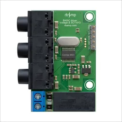
BASIC SCT-UI1 / UI2 / UI3 / UI5 / UI7
Wattmeter modules for SCT-013 clamps, one to seven channels
One voltage input and up to seven current channels per board, I²C. Clamps not included.
View detailsBASIC measurement modules
One metering board and one serial port per circuit turns into a nest of wires. One BASIC module watches up to seven circuits on a two-wire bus, and several modules share the same bus.
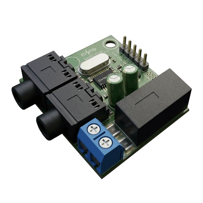
01 / Series
Use your own SCT-013 clamp and select its rated current in software. The module is calibrated for the SCT-013 family; the accuracy you get depends on the individual sensor (see
the table).
Choose SCT if:
A through-core sensor ships with every channel and is calibrated together with it at the factory; the sensor is labelled with its channel. Nothing to configure, no sensor-to-sensor variation.
Choose CT if:
Both series use the same register map, the same libraries and the same API. Choosing one never locks you out of the other — they share one bus.
02 / Which model
For your own SCT-013 sensor: 3.5 mm jack, clip-on without power-down. Sensor not included — use your SCT-013 (5…100 A).
A clamp on every channel, calibrated with the channel at the factory and marked with its number: nothing to select or configure.
03 / Models
Wattmeter modules for SCT-013 clamps, one to seven channels
One voltage input and up to seven current channels per board, I²C. Clamps not included.
View details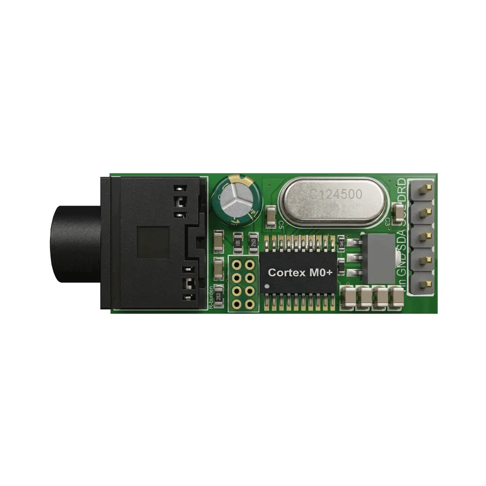
Current-only modules for SCT-013 clamps
One to three current channels, no voltage input, I²C. Clamps not included.
View detailsOne voltage input and 1/2/3/5/7 channels. Clamp ratings 1, 5, 10, 20, 30, 50 or 100 A, the same on all channels of a module; window 6 mm (1–10 A), 10 mm (20–50 A), 16 mm (100 A); 1 m cable with a plug-in connector. No price until release · Sensor included, calibrated with its channel.
05 / Accuracy
Accuracy depends on the complete measuring system. A reading is the module plus the sensor — and there is a floor below which a current is seen but not measured accurately.
BASIC modules (SCT-UI series) with your own SCT-013 sensor — resistive load, measured at 50 Hz. Modules with a factory-paired CT sensor, and STD modules, are specified separately — this table does not apply to them.
| Characteristic | SCT-013-005 | SCT-013-010 | SCT-013-020 | SCT-013-030 | SCT-013-050 | SCT-013-060 | SCT-013-100 |
|---|---|---|---|---|---|---|---|
| Detectable floor (the reading with no load) | ~3 mA | 6–9 mA | ~10 mA | ~13 mA | ~25 mA | ~30 mA | ~60 mA |
| Readable floor (error ≤ 10 %; 0.5 % of rating) | 25 mA | 50 mA | 0.10 A | 0.15 A | 0.25 A | 0.30 A | 0.50 A |
| Class near the floor, UI1 / UI2 / UI3 (±1 % of the average, from ~0.7 % of rating) | from 35 mA | from 70 mA | from 0.14 A | from 0.21 A | from 0.35 A | from 0.42 A | from 0.70 A |
| Class near the floor, UI5 / UI7 (±0.5 %, from 2 % of rating) | from 0.10 A | from 0.20 A | from 0.40 A | from 0.60 A | from 1.0 A | from 1.2 A | from 2.0 A |
| Class in the working range (5–100 % of rating, of the average) | ≤ 0.5 % | 0.16–0.35 % | ≤ 0.5 % | 0.53 % | ≤ 0.5 % | ≤ 0.5 % | 0.47 % |
| Tolerance of the sensor unit (added on top of the class) | ≤ 0.8 % | 0.5–1.0 % | 0.8 % | 1.2 % | 0.7 % | 0.3–0.4 % | 0.45 % |
| Step of one instantaneous value | 4.1 mA | 8.1 mA | 16 mA | 24 mA | 41 mA | 49 mA | 83 mA |
| Top of the range (clipping, sine wave) | ~6.0 A | 11.9 A | ~24 A | 35 A | ~60 A | ~72 A | ~117 A |
06 / Rating
A × 230 V = W (at 120 V: A × 120 V)
Sizing the clamp. Say you want to see the whole house. Your main breaker is 40 A, so you reach for an SCT-013-060 — the next rating above the breaker, with room to spare: the clamp's range tops out at about 72 A, so a 40 A main never gets near the top.
What you will see. Now look down the 60 A column. Anything from about 0.3 A upwards is a reading you can use — roughly 70 W at 230 V. From about 0.42 A (around 100 W) the module holds ±1 % of the average on UI1, UI2 and UI3. From 3 A (5 % of the rating, about 700 W) up to the full 60 A it reads within half a percent, plus the sensor's own 0.3–0.4 %. A 2 kW boiler draws about 8.7 A — comfortably inside. A 7 kW charger at 30 A — inside. The oven, the heat pump, the whole evening peak — all inside. For a house input, this clamp is the right tool.
What you will not see. Below 0.3 A the module still sees current — the detectable floor is about 30 mA — but the reading is noisy and you should not trust the number. A phone charger drawing 10 W is about 43 mA: you will see that something is on, you will not get a figure you can rely on. The house's night baseline — the router, the TV on standby, the fridge electronics — might be 40 W, or 0.17 A. On the 60 A clamp that is above detectable, below readable: the graph shows a floor, the number is a guess. If "what draws power when everything is off" is the question you want answered, a 60 A clamp on the input will not answer it.
What does. A smaller rating, closer to the load. The same table says a 5 A clamp reads usable values from 25 mA — about 6 W — and holds its class from 35 mA, about 8 W. Put it on the circuit that feeds the living room and the night baseline becomes a number. On UI5 and UI7 modules the near-floor class starts higher (from 2 % of the rating), so for small loads prefer UI1–UI3 or keep the rating small.
Pick the smallest rating that still clears the circuit's maximum current. House input on a 40 A main → 60 A. A 63 A main → 100 A. A floor or sub-panel on a 25 A breaker → 30 A. A boiler, an oven, a charger on a 16–32 A breaker → 20–50 A. A single appliance, a lamp circuit, the "what is on at night" question → 5 or 10 A.
The floor scales with the rating: a 60 A clamp holds its class from about 100 W, a 5 A clamp from about 8 W.
You can mix: one 60 A clamp on the input for the total, 5–20 A clamps on the branches you care about — all on the same bus, each channel with its own rating set in software.
And if the point is microamperes — standby, vampires, export that has to be counted — that is what STD is built for.
One more thing the table says quietly: these are SCT-013 figures. A real clamp's own error is about 1 %, and it can drift with age and temperature. That is why the CT series exists — each sensor is calibrated with the channel it ships with, so sensor-to-sensor variation is out of the question.
07 / Clamp
Already have SCT-013 sensors?
CT series: don't choose a sensor — get a calibrated pair. Pick the number of channels and the rating; the sensors arrive labelled per channel, already calibrated with the module. Connect each sensor to the channel it is labelled for — the calibration belongs to that pair.
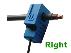
One conductor. The clamp goes around ONE conductor — a single live wire, or a single neutral. Around a two-wire cord the two currents cancel and the reading stays at zero.
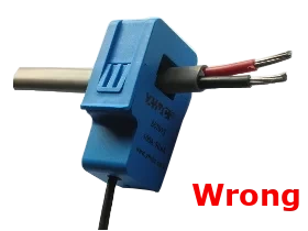
08 / Data
Ready physical units every measurement window (~100 ms on current firmware), per channel. No signal processing on your side.
Full register map| U_rms | RMS voltage · V |
|---|---|
| U_peak | peak voltage · V |
| In_rms | RMS current, per channel · A |
| In_peak | peak current, per channel · A |
| Pn_real | active power, per channel, signed (+ consumption, − export) · W |
| Qn_reac | reactive power, per channel · var (≥ 0) |
| PFn | power factor · −1…+1 |
| AC_FREQ | line frequency · Hz (50 or 60, detected) |
| PERIOD_AVG_P_W | average power over a period · W |
| PERIOD_MAX_P_W | peak power over a period · W |
UI5 and UI7 read channels 3 and up through the channel access window; the libraries handle it. Energy (Wh) is integrated by your controller from period snapshots — the libraries do it for you. The module does not keep an energy counter.
09 / Start
VCC, GND, SDA, SCL — a standard I²C slave — and clip the sensor.
ESPHome component, Arduino library, ESP-IDF component or pip install rbamp
Volts, amperes, watts and energy in your dashboard.
Writing your own driver? Six raw-register tutorials:
Arduino·
MicroPython·
ESP-IDF·
Python on SBC·
ESPHome10 / Why a bus
Most controllers have one UART, usually taken by the console. rbAmp talks I²C: many modules on two shared pins.
The module does the sampling and true-RMS maths and returns float values. No interrupts, no sine-catching, no filter code.
One command closes and opens a measurement period with no read-reset gap — no dropped or double-counted samples at the boundary. Energy per minute, 15 minutes, hour, or per event (a contactor, a charging session).
Documented register and command map; MIT libraries for ESPHome, Arduino, ESP-IDF and Python. Any stack, or your own code.
An isolation barrier separates the measurement side (clamp, voltage input) from the side you wire (I²C). The module's GND is not connected to phase or neutral, so connecting it to a 5 V controller is safe.
SafetySDA, SCL and the data-ready pin connect straight to ESP32 or Raspberry Pi GPIO; power the module at 5 V (4.5–5.5 V).
11 / Periods
BASIC reports period snapshots; the energy total lives on your controller, where the library integrates and persists it (ESPHome: in NVS, survives a reboot). The module itself keeps no counter — that is what
STDadds.
| CMD_LATCH_PERIOD | One command freezes the period's average and peak power; the next period opens in the same moment. |
|---|---|
| General Call | Enable it per module and every module on the bus freezes at the same instant — a whole-house balance from one moment. Masters detect modules that opted out and snapshot them one by one. |
| master clock | One clock — your controller's — for all modules removes per-module drift. |
Live power is signed, but period energy on BASIC is consumption only. For import and export counters kept on the device, see
STD.
Source: Docs › BASIC › Period metering
12 / One bus
| Wires and address | Two wires. Address 0x50 by default, changeable to 0x08…0x77 with a two-phase commit; identify modules by their ID, not by address. |
|---|---|
| Speed | 50 kHz on ESP32 / ESP8266 hosts (a driver limitation), 100 kHz on other hosts; 400 kHz is not recommended. |
| Supply and logic | Supply 5 V (4.5–5.5 V); logic 3.3 V, 5 V-tolerant; optional data-ready pin, one ~10 µs pulse per window. |
| Modules per bus | Up to about 16 modules on one bus — the limit is bus capacitance (≤ 400 pF at 100 kHz), not the address range. |
| Bus length | We recommend up to 0.15 m between the module and the controller: keep the controller next to the module. Longer runs (twisted pair, an I²C buffer, a differential bus) are your own design. In a cabinet, shield the cable. |
13 / Safety
The side you wire to your controller — VCC, GND and the I²C bus to an ESP32, Arduino or Raspberry Pi — is low-voltage and galvanically isolated from the measurement side; the module's GND is not connected to phase or neutral. The measurement side connects to mains: current through a clamp around one insulated conductor, voltage (UI models) through the L and N terminals, with a fuse in L. For work inside an electrical panel, call a qualified electrician. Do not open the module's enclosure.
Safety · Source: Docs › BASIC › Hardware connection
14 / BASIC vs STD
Watch circuits and appliances; consumption only; energy on your controller.
Counters on the device, import and export, Modbus RTU as a standalone meter, microampere resolution — on the same bus. Measuring the input or an inverter? You need STD.
A pre-flashed ESP32 and a shield with connectors for the modules. Reads BASIC modules too.
15 / Questions
SCT series: no — use your SCT-013. CT series: yes, calibrated with its channel.
No. The module carries the calibration for the SCT-013 family; you select the rating. For a sensor calibrated with its channel, take the CT series.
The smallest rating above your maximum current; the guide under the accuracy table walks through it.
Power the module at 5 V (4.5–5.5 V). The bus runs on 3.3 V logic and is 5 V-tolerant, so ESP32, Raspberry Pi and 5 V Arduino boards connect directly.
Up to about 16, limited by bus capacitance; give each module its own address before connecting them in parallel.
Live power is signed; period energy on BASIC is consumption only. For export counters, take STD.
No. Use ESPHome, your own code or any I²C master; rbgrid is one ready master firmware.
Pick the channel count and the clamp rating; the module does the measuring and your controller just reads it.