
The problem this solves
Your utility meter says the house is pulling about 3.9 kW right now. It won't tell you that the water heater is ~2.2 kW of it, the AC compressor another ~1 kW, and the rest is sockets and lights. To see per circuit you need a meter per circuit — and the usual DIY meter, a PZEM on a UART, is one device per serial port. Two of them already means bit-banged serials fighting the ESP's WiFi; a whole panel is out of the question. The commercial per-circuit boxes (Emporia and friends) solve the wiring but tie you to their cloud.
rbAmp scales the other way. A multi-channel BASIC module measures voltage and current on each of its channels and computes real active power and energy per channel on the module itself — and it talks I²C, a bus, so one ESP32 reads a stack of them over the same two signal wires. One ESP32, real numbers for every circuit, in your own Home Assistant. This is the build B1 promised — the whole panel, per circuit.
What you'll have
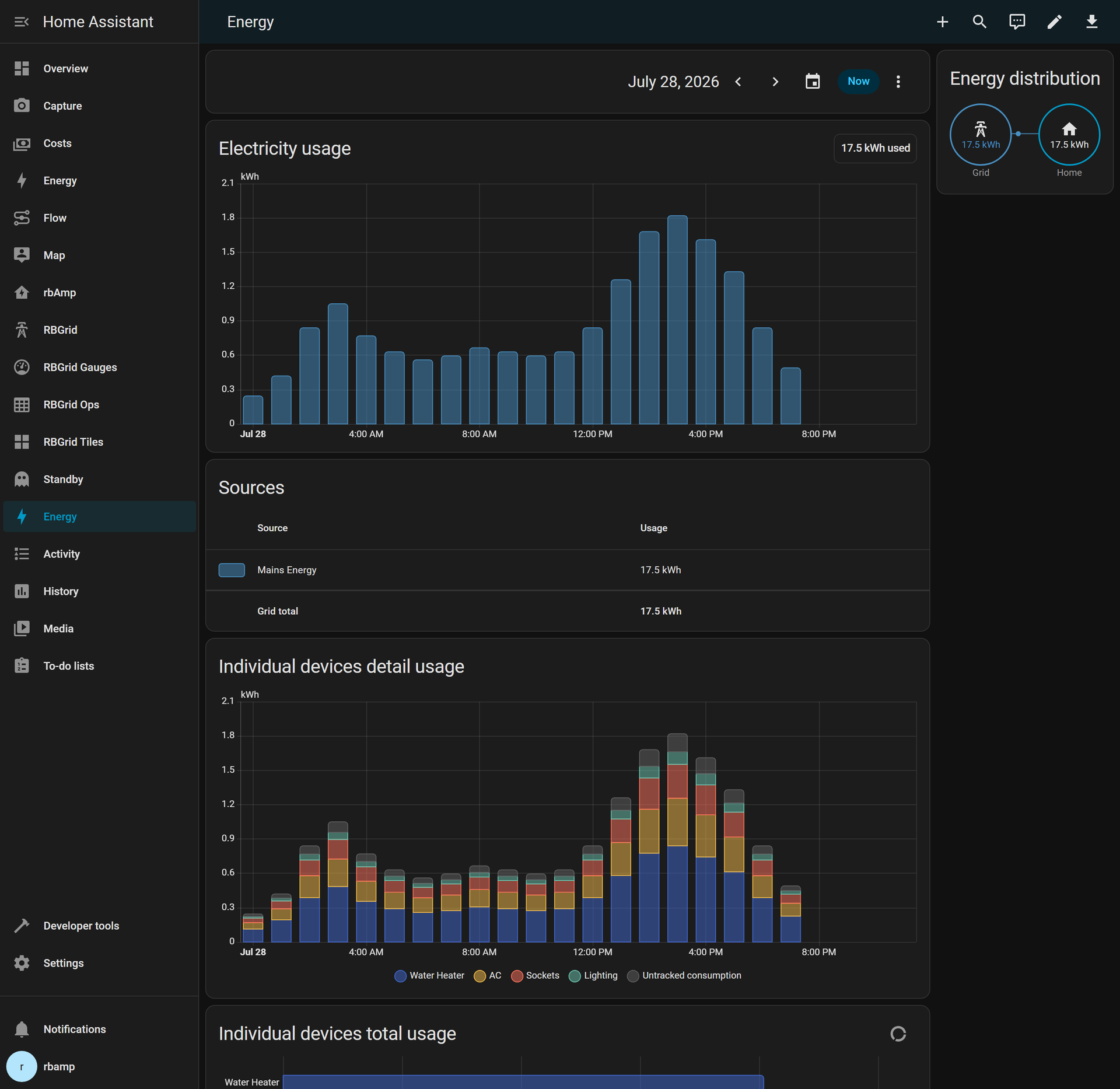 One ESP32, one bus: the mains total plus every branch, broken out per circuit — real energy, not an estimate.
How it scales: UI modules on one bus
The architecture is the whole point, so it's worth thirty seconds up front:
- Each module measures voltage and current — so it reports real power. A UI-series module samples V and
its currents together and computes
mean(u·i)per channel on-chip: real active power (W) and energy (Wh), power factor included, no host-side guessing. - Up to 3 circuits per module. UI1 / UI2 / UI3 = one voltage reference + 1 / 2 / 3 current channels. A UI3 meters three circuits; two UI3 modules meter six. (5- and 7-channel modules are on the roadmap.)
- It's a bus, not a serial port. Every module shares the same SDA/SCL. Add circuits by adding modules —
no new ESP32, no new UART, no
SoftwareSerial. - Synchronized across modules. Run the fleet in one group and a single I²C General-Call (GC) broadcast latches every module's period on the same instant, so the per-circuit energies reconcile against the mains feed.
Real active power, measured per circuit — not disaggregated
This is where a monitoring build has to be honest, so here it is plainly. (Per circuit means a CT on every branch — a real measurement — not one whole-home sensor disaggregating the total into per-appliance guesses the way single-point NILM monitors do.)
- The power and energy are real, computed on the module. Because each channel has both voltage and current,
the module computes true active power (
P = mean(u·i), power factor and waveform distortion included) and accumulates real watt-hours per channel. There's no "current × assumed voltage" apparent-power estimate and no Riemann-sum guesswork in Home Assistant — HA receives finished, per-circuit Wh. - What Basic doesn't do: a Basic module measures consumption (import), single measurement range. If you need to separate import from export (solar feed-in) or a wider dynamic range, that's the Standard series — it adds bidirectional metering and multi-range accuracy on top of the same per-channel real power.
- Not a revenue meter. Monitoring-grade and calibrated, but not certified for billing.
(Want cheap, real-time load control instead of accurate energy accounting — current limits, over-load alerts, shedding? That's a different job for the current-only I-modules — see real-time load control.)
Bill of materials
| Item | Why | Where |
|---|---|---|
| 2× rbAmp Basic UI3 (V + 3 currents each = 6 channels) | real power + energy on every circuit | UI-series wattmeter |
| 6× SCT-013 CT (rating per circuit: 50 A mains/EV, 30 A appliances, 5 A lighting) | one clamp per measured conductor | SCT-013 current transformer |
| 1× ESP32 dev board | the single host for the whole panel | — |
| bus wiring (SDA/SCL/3V3/GND) | one I²C bus to both modules | — |
Prices: see each product page. Scale by adding UI modules on the same bus — no extra ESP. (No external pull-up resistors — the modules have them on board. See addressing below for multi-module buses.)
Get the hardware: rbAmp UI-series wattmeter (SCT-013), 1–7 channels
Safety first — this is live-panel work
⚠️ A panel is more dangerous than a single appliance, and this project puts several CTs inside one. Every CT clamps around an insulated conductor — you never cut or strip live wire — but opening the panel, routing CTs, and working among live busbars is qualified-electrician territory. Kill the main, verify dead, and if you're not certain you're competent in the panel, have an electrician place the CTs and bring the low-voltage leads out to where you wire the modules. Label every CT to its breaker before you close up.
Address each module (one-time)
Modules ship at 0x50. A fleet needs unique addresses, so the second module gets 0x51, using ESPHome's
new_address: one-shot — no factory mode, no extra tools. Do it one module at a time, with the other
disconnected so there's no address clash.
Per additional module:
1. Connect only that module to the bus.
2. Flash a scratch config with its current and target address:
yaml
   rbamp:
     id: meter
     address: 0x50          # current
     new_address: 0x51      # target — DELETE this line after it succeeds
3. Watch the log for the re-probe success line, then remove new_address: and set address: 0x51.
4. Label the module + its CTs to their breakers. Repeat for 0x52… if you add more.
Pull-ups (multi-module buses). The modules carry I²C pull-ups on board — you never add external ones. But on a bus of several modules those on-board pull-ups sit in parallel and become too strong. Keep one set active (the first module) and disable the pull-ups on every other module (jumper / solder-cut per the hardware guide). For one or two modules you can leave them all as-is.
The one YAML
One file drives the whole panel: two UI3 modules at 0x50/0x51, six channels, each reporting real V/I/P/
Wh/PF. Both modules run in one fleet group so their periods latch together.
esphome:
  name: rbamp-panel-ui
esp32:
  board: esp32dev
  framework:
    type: arduino
wifi:
  ssid: !secret wifi_ssid
  password: !secret wifi_password
api:
ota:
  - platform: esphome
logger:
i2c:
  sda: GPIO21
  scl: GPIO22
  frequency: 50kHz   # ESP-IDF i2c_master driver + the module's I²C recovery window interact at
                     # 100 kHz → intermittent read NACKs on ESP32. 50 kHz is the robust setting.
                     # STM32 / RP2040 / Linux-SBC masters run this module at 100 kHz fine.
  scan: true
external_components:
  - source: github://rb-amp/[email protected]
    components: [rbamp]
# Two UI3 modules, one synchronized fleet.
rbamp:
  - id: mod_heavy
    address: 0x50
    update_interval: 10s
    ct_models: [SCT_013_050, SCT_013_030, SCT_013_030]   # ch0 mains · ch1 water heater · ch2 AC
    fleet_gc_enable: true
    group_id: 1
  - id: mod_light
    address: 0x51
    update_interval: 10s
    ct_models: [SCT_013_005, SCT_013_030, SCT_013_050]   # ch0 lighting · ch1 sockets · ch2 EV
    fleet_gc_enable: true
    group_id: 1
sensor:
  # ── Module A @ 0x50: mains + water heater + AC — one voltage sense, real P/Wh per channel ──
  - platform: rbamp
    rbamp_id: mod_heavy
    voltage:        { name: "Mains Voltage" }
    frequency:      { name: "Mains Frequency" }
    current:        { name: "Mains Current" }
    power:          { name: "Mains Power" }
    energy:         { name: "Mains Energy" }             # → Energy Dashboard "Grid consumption"
    power_factor:   { name: "Mains Power Factor" }
    current_1:      { name: "Water Heater Current" }
    power_1:        { name: "Water Heater Power", id: p_heater }
    energy_1:       { name: "Water Heater Energy" }      # → Energy Dashboard "Individual device"
    power_factor_1: { name: "Water Heater Power Factor" }
    current_2:      { name: "AC Current" }
    power_2:        { name: "AC Power", id: p_ac }
    energy_2:       { name: "AC Energy" }
    power_factor_2: { name: "AC Power Factor" }
  # ── Module B @ 0x51: lighting + sockets + EV (voltage marked internal — same mains rail) ──
  - platform: rbamp
    rbamp_id: mod_light
    voltage:        { name: "Mains Voltage (mod B ref)", internal: true }
    current:        { name: "Lighting Current" }
    power:          { name: "Lighting Power", id: p_lighting }
    energy:         { name: "Lighting Energy" }
    power_factor:   { name: "Lighting Power Factor" }
    current_1:      { name: "Sockets Current" }
    power_1:        { name: "Sockets Power", id: p_sockets }
    energy_1:       { name: "Sockets Energy" }
    power_factor_1: { name: "Sockets Power Factor" }
    current_2:      { name: "EV Current" }
    power_2:        { name: "EV Power", id: p_ev }
    energy_2:       { name: "EV Energy" }
    power_factor_2: { name: "EV Power Factor" }
  # ── Sum of branches vs mains — should track within a few % on a fully-metered panel ──
  - platform: template
    name: "Branches Power Sum"
    device_class: power
    state_class: measurement
    unit_of_measurement: W
    update_interval: 10s
    lambda: |-
      float s = 0;
      if (id(p_heater).has_state())   s += id(p_heater).state;
      if (id(p_ac).has_state())       s += id(p_ac).state;
      if (id(p_lighting).has_state()) s += id(p_lighting).state;
      if (id(p_sockets).has_state())  s += id(p_sockets).state;
      if (id(p_ev).has_state())       s += id(p_ev).state;
      return s;
See it in Home Assistant
After the flash, the boot log confirms both modules on the one bus, latching together as a fleet:
[i2c ] Found i2c device at address 0x50
[i2c ] Found i2c device at address 0x51
[rbamp] mod_heavy: variant=UI3, fleet_gc=on, group=1
[rbamp] mod_light: variant=UI3, fleet_gc=on, group=1
[rbamp] GC latch enabled fleet-wide: 2 modules (6 channels) in group 1- Adopt the rbamp-panel-ui node (Settings → Devices & Services). You get six circuits, each with real current, power, energy and power factor.
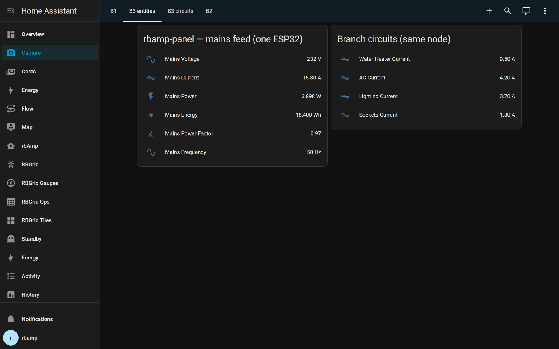
- Build a per-circuit view — a glance card ranks your loads by real power, live.
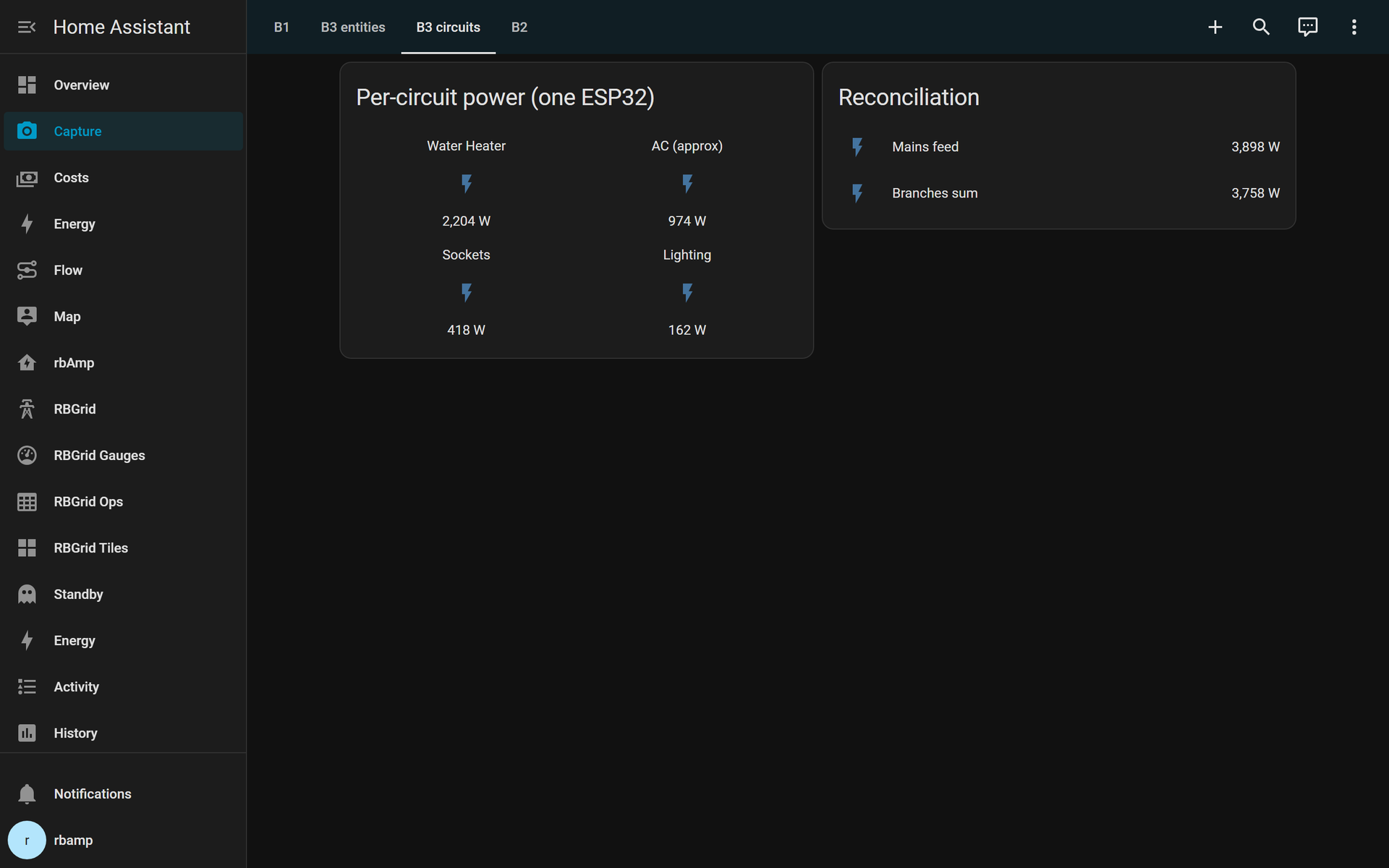
- Branch sums ≈ feed. With every module in one
group_id, a single broadcast latches them on the same instant, so the Branches Power Sum tracks Mains Power to within a few percent — the gap is your un-metered small loads. Because these are real active-power figures, that reconciliation actually holds (it wouldn't with apparent-power estimates).
Add it to the Energy Dashboard
- Grid consumption: point it at
sensor.mains_energy— the real, measured total. - Individual devices: add each circuit's
..._energysensor. These are real per-circuit watt-hours computed on the module — drop them straight into the Energy Dashboard's Individual devices panel for an honest per-circuit breakdown, no Riemann-sum artifacts.
What's next
- Real-time load control. Want to cap a circuit, alert on over-consumption, or shed load before the main breaker trips? That's a job for the fast, cheap current-only I-modules and a few HA automations. (See real-time load control with rbAmp.)
- Honest three-phase. One synchronized sample set across all three phases, under the Standard 3-phase release. (Coming in this series.)
- Hunt the vampires. With every circuit metered, the standby floor becomes a sortable list. (Coming.)
Start here if you haven't got a single module running yet: rbAmp in the Home Assistant Energy Dashboard in 15 minutes. For the bus wiring and addressing detail, see the ESPHome hardware guide and the API reference.
Related: the rbAmp UI series — 1 to 7 channels on one I²C bus, and the head-to-head rbAmp vs PZEM-004T.
[newsletter / early-adopter subscribe block — deploy session inserts the site's standard subscribe snippet]