
If you've read why three single-phase meters can't measure your 3-phase power, you know the trap: three independent meters sample at different instants, so their numbers don't add up. This is the build that does it right — three rbAmp UI modules on one ESP32, one per phase, each measuring its own phase's real power and all three latched on the same instant. The result lands in Home Assistant as honest per-phase data plus a coherent three-phase total that reconciles with your utility meter.
What you'll build
- Real per-phase voltage, current, active power, energy (kWh) and power factor for L1 / L2 / L3.
- A coherent three-phase total active power (the three phases summed on one synchronized latch).
- Everything on one ESP32 over a single I²C bus — no second microcontroller, no round-robin ADC.
- All of it in the Home Assistant Energy Dashboard.
Bill of materials
| Item | Qty | Notes |
|---|---|---|
| rbAmp Basic Wattmeter (UI1) | 3 | one per phase — voltage + current + on-chip real power · product |
| SCT-013 current transformer | 3 | one per phase, rating to match each phase's service capacity · product |
| ESP32 dev board | 1 | any esp32dev-class board |
| Jumper wires | — | the shared I²C bus (SDA/SCL/3V3/GND) |
Each UI1 module needs its own phase voltage as well as its CT. Wire each module's voltage input to the phase it's metering (L1→module A, L2→module B, L3→module C) — that per-phase voltage pairing is exactly what makes the measurement coherent. Read the safety section below before you wire anything — the voltage taps are live-conductor connections, not clip-on clamps.
Safety first — the voltage taps are live-conductor work
⚠️ This is not a clip-on-clamp build. Unlike a non-invasive CT that clamps around an insulated wire, each module here needs a voltage tap — a galvanic connection to a live phase conductor. That is mains-voltage work and qualified-electrician territory. If you're not certain you're competent inside a live panel, stop and have an electrician make the in-panel connections.
Before you touch anything: kill the main breaker and verify the conductors are dead with a meter — never assume. Then:
- Fuse or breaker every voltage tap. Each phase-voltage lead to a module comes off its own suitably rated fuse or protected branch — never an unfused tap straight off a busbar.
- Use correctly rated wire and insulation for the tap leads (mains-rated conductor, adequate gauge, full insulation up to the module terminal). Keep the low-voltage I²C side (SDA / SCL / 3V3 / GND) physically clear of the mains-side wiring.
- The CT side stays non-invasive — the SCT-013 still just clamps around its phase conductor; you never cut or strip a live wire for the current side.
- Label every tap and CT to its phase and breaker before you close the panel.
Three-phase mains voltage is lethal. When in doubt, bring only the low-voltage module leads out of the panel and have a qualified electrician do the live connections.
Wire the bus
All three modules share one I²C bus off the ESP32:
ESP32 GPIO21 (SDA) ─┬── UI1 phase-A  (CT on L1, voltage tap on L1)
                    ├── UI1 phase-B  (CT on L2, voltage tap on L2)
                    └── UI1 phase-C  (CT on L3, voltage tap on L3)
ESP32 GPIO22 (SCL) ─┘ + shared 3V3 and GND to all three- Clamp each module's CT around one phase conductor, arrow toward the load.
- On-board pull-ups: keep them active on the first module in physical wire order and disable them on the other two — one pull-up pair per bus, never external. (See the module hardware doc.)
Give each module its own address
All modules ship at I²C address 0x50. Three on one bus need three addresses — 0x50, 0x51, 0x52. Assign
the second and third once each, one module at a time with the others disconnected so there's no clash. On
current firmware this is a production-mode operation — no factory mode, no extra tools:
- Connect only the module you're re-addressing.
- Flash a scratch config with
address: 0x50andnew_address: 0x51(then0x52for the third). - Watch the ESPHome boot log confirm the change, then set
address: 0x51, delete thenew_address:line, and move on to the next module.
(Full mechanics: ESPHome API reference → new_address.)
The ESPHome config
Three UI1 modules at 0x50 / 0x51 / 0x52, one synchronized fleet, live per-phase data plus the coherent total.
Set your CT sizes and Wi-Fi secrets, flash:
# Three-phase energy monitoring: 3× rbAmp UI1 on one ESP32, one I²C bus.
#   GPIO21 SDA ─┬─ UI1 @0x50  (phase A: V+I on L1)
#              ├─ UI1 @0x51  (phase B: V+I on L2)
#              └─ UI1 @0x52  (phase C: V+I on L3)
# Each module computes its phase's real power on-chip; fleet_gc_enable + group_id
# latch all three on one broadcast instant (<10 µs skew).
# Compile-verified: ESPHome 2026.5.3, github://rb-amp/[email protected].
esphome:
  name: rbamp-3phase
esp32:
  board: esp32dev
  framework:
    type: arduino
wifi:
  ssid: !secret wifi_ssid
  password: !secret wifi_password
api:
ota:
  - platform: esphome
logger:
i2c:
  sda: GPIO21
  scl: GPIO22
  frequency: 50kHz   # ESP-IDF i2c_master driver + the module's I²C recovery window interact at
                     # 100 kHz → intermittent read NACKs on ESP32. 50 kHz is the robust setting.
                     # STM32 / RP2040 / Linux-SBC masters run this module at 100 kHz fine.
  scan: true
external_components:
  - source: github://rb-amp/[email protected]
    components: [rbamp]
# ─── Three UI1 modules in the same GC-LATCH fleet ────────────────────────────
rbamp:
  - id: phase_a
    address: 0x50
    update_interval: 10s
    latch_interval: 60s
    ct_model: SCT_013_050         # mains phase — pick to match your service capacity
    fleet_gc_enable: true
    group_id: 1
  - id: phase_b
    address: 0x51
    update_interval: 10s
    latch_interval: 60s
    ct_model: SCT_013_050
    fleet_gc_enable: true
    group_id: 1
  - id: phase_c
    address: 0x52
    update_interval: 10s
    latch_interval: 60s
    ct_model: SCT_013_050
    fleet_gc_enable: true
    group_id: 1
# ─── HA entities — per-phase real V/I/P/Wh/PF + 3-phase total ────────────────
sensor:
  # ══ Phase A (L1) ═════════════════════════════════════════════════════════
  - platform: rbamp
    rbamp_id: phase_a
    voltage:
      name: "Phase A Voltage"
    current:
      name: "Phase A Current"
    power:
      name: "Phase A Power"
      id: p_phase_a
    energy:
      name: "Phase A Energy"                  # ← per-phase kWh accumulator
    power_factor:
      name: "Phase A Power Factor"
    frequency:
      name: "Phase A Frequency"               # publish freq from phase A only
  # ══ Phase B (L2) ═════════════════════════════════════════════════════════
  - platform: rbamp
    rbamp_id: phase_b
    voltage:
      name: "Phase B Voltage"
    current:
      name: "Phase B Current"
    power:
      name: "Phase B Power"
      id: p_phase_b
    energy:
      name: "Phase B Energy"
    power_factor:
      name: "Phase B Power Factor"
  # ══ Phase C (L3) ═════════════════════════════════════════════════════════
  - platform: rbamp
    rbamp_id: phase_c
    voltage:
      name: "Phase C Voltage"
    current:
      name: "Phase C Current"
    power:
      name: "Phase C Power"
      id: p_phase_c
    energy:
      name: "Phase C Energy"
    power_factor:
      name: "Phase C Power Factor"
  # ── 3-phase total active power (Σ per-phase real P) ───────────────────────
  # All three modules latch on the same broadcast instant (fleet_gc_enable),
  # so the summed instantaneous P values are coherent. Reads happen
  # sequentially after the latch, but the frozen P values reflect the same
  # wire moment. Skew: <10 µs chip-side; negligible for any real load.
  - platform: template
    name: "Total 3-Phase Active Power"
    device_class: power
    state_class: measurement
    unit_of_measurement: W
    accuracy_decimals: 1
    update_interval: 10s
    lambda: |-
      float total = 0;
      if (id(p_phase_a).has_state()) total += id(p_phase_a).state;
      if (id(p_phase_b).has_state()) total += id(p_phase_b).state;
      if (id(p_phase_c).has_state()) total += id(p_phase_c).state;
      return total;
Two knobs worth understanding:
fleet_gc_enable: true+group_id: 1put all three modules in one synchronized fleet. Once a minute the ESP32 sends a single General-Call "latch now" frame and every module freezes its period accumulator on the same instant (sub-10-µs skew) — that's what makes the three-phase total coherent instead of three independently-sampled numbers.latch_interval: 60s(rbAmp ESPHome v1.4) decouples the synchronized LATCH from the live read cadence: the dashboard refreshes voltage / current / power everyupdate_interval(10 s), while the coherent energy-latch burst runs just once a minute. kWh stays exact either way — the master integrates over real wall-clock time. Drop the line for single-cadence v1.3 behaviour.
Add it to Home Assistant
- Flash and let the node come up — Home Assistant auto-discovers it via the ESPHome API. You'll see the per-phase entities plus Total 3-Phase Active Power.
- Settings → Devices & Services → Energy. Add each phase's Energy sensor (
Phase A/B/C Energy) as a grid-consumption source — the dashboard sums them for whole-home consumption. - Build a quick Lovelace view with the three per-phase powers and the total for a live per-circuit picture.
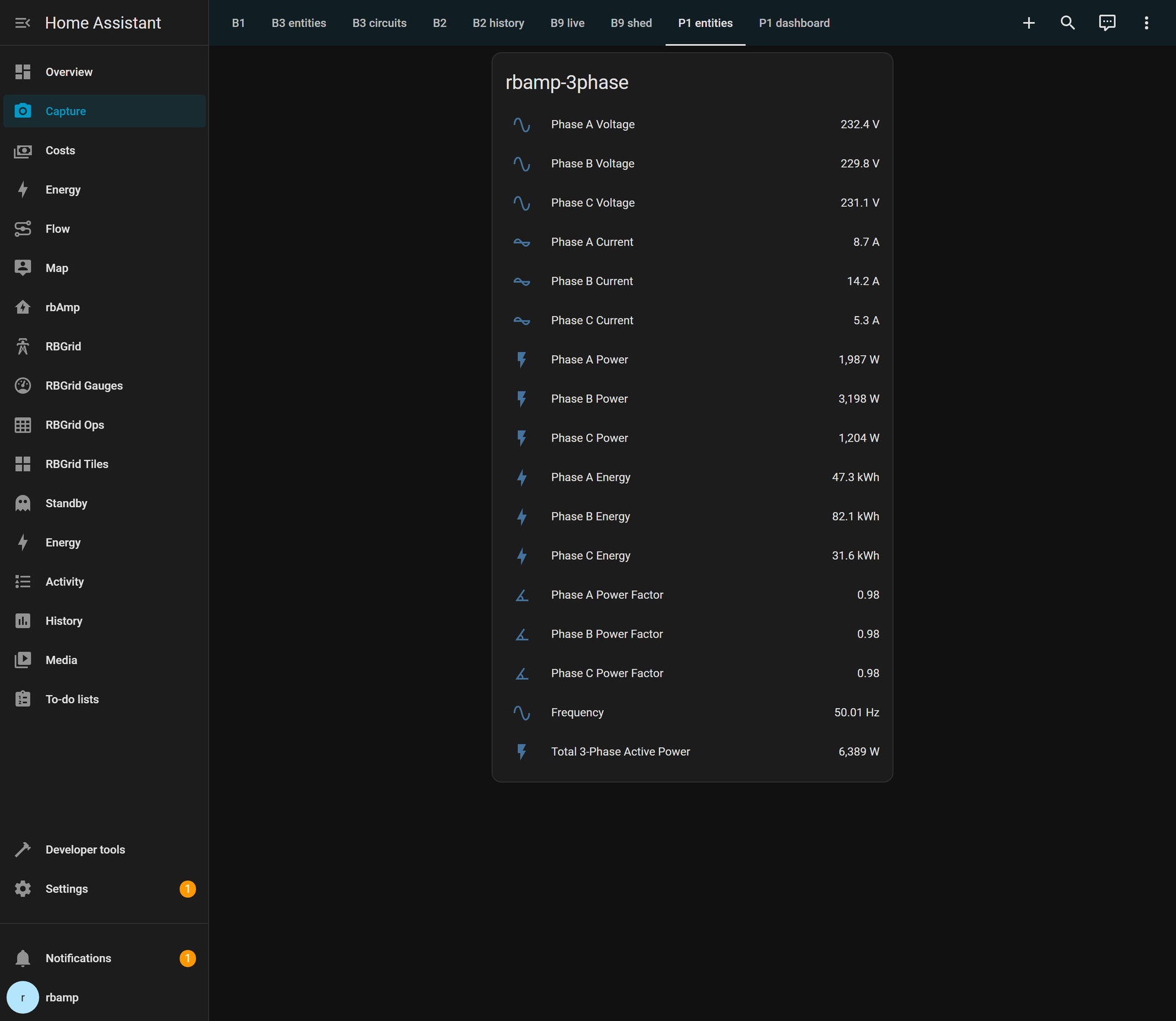
The rbamp-3phase node in Home Assistant: all 17 entities reporting — per-phase V/I/P/Wh/PF, frequency, and the coherent total.
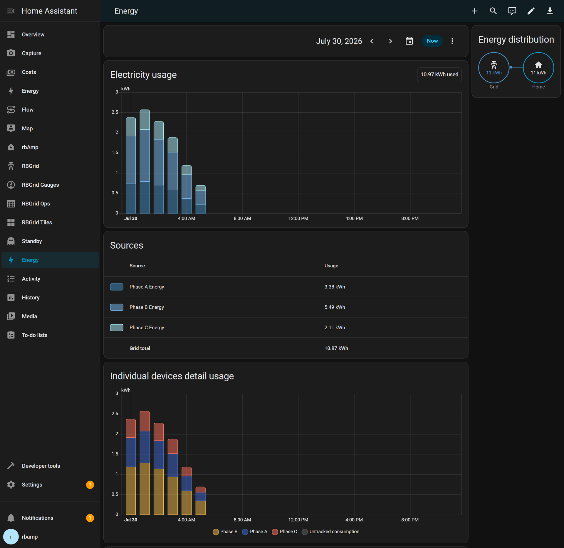
The HA Energy Dashboard with per-phase grid consumption: each phase is an individual source, stacked bars show the unbalance.
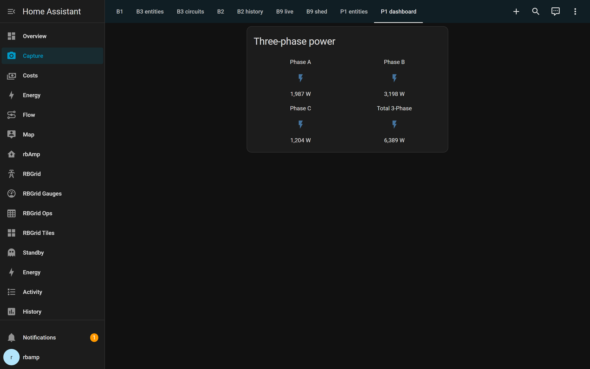
A glance card showing per-phase active power and the coherent three-phase total — the imbalance is visible at a glance.
Verify it's wired right
- The boot log's I²C scan should list all three addresses:
[i2c] Found i2c device at address 0x50
[i2c] Found i2c device at address 0x51
[i2c] Found i2c device at address 0x52- Under a known single-phase load on one phase, only that phase's power should move.
- The three per-phase powers should sum to Total 3-Phase Active Power at every update.
- If a phase reads a suspiciously round fraction of what you expect, check that its voltage tap is on the same phase as its CT — the coherent pairing is the whole point (see the physics).
Why this is accurate
Each module measures its phase's voltage and current together and computes real active power on-chip; the synchronized latch freezes all three on one instant. That's coherent per-phase integration — the sub-1% tier, versus the 15–50% error of measuring one phase and tripling it. The full reasoning is in the companion article: why three single-phase meters can't measure your 3-phase power.
Prefer one board? A dedicated single-board variant (U3I3 — all three phases on one board, one I²C address) is in development. It’s on the roadmap, not shipping yet; subscribe below and we’ll say when it lands. Until then, this three-module fleet is the honest-numbers path you can build today.
What's next
- Understand it first: Why three single-phase meters can’t measure 3-phase power — why three single-phase meters can’t give you true 3-phase power.
- Start smaller: The whole panel on one ESP32 — one ESP32 metering the whole panel before you go three-phase.
- The hardware: The rbAmp UI series — 1 to 7 channels on one bus — how 1–7 channels share a single I²C bus.
- Questions? the rbAmp FAQ — accuracy, isolation, addressing and more.
[newsletter / early-adopter subscribe block — deploy session inserts the site's standard subscribe snippet]