01 · Overview
📦 GitHub:
rb-amp/rbamp-esphome— component source, example YAML, changelog (v1.6.0).
Install: addexternal_components: [source: github://rb-amp/rbamp-esphome@main]to your YAML (see Quick Start).
What rbAmp is
rbAmp is a compact hardware module for precise measurement of AC mains parameters. From the integrator's point of view it is a regular I²C slave: apply power, read a register — get a ready value in physical units. No signal processing is required on the master side. Factory calibration is done once in production and stored in the module's flash; the user only needs to choose the CT clamp model (see Sensor Selection) and wire up the bus.
Data flow (one-liner)
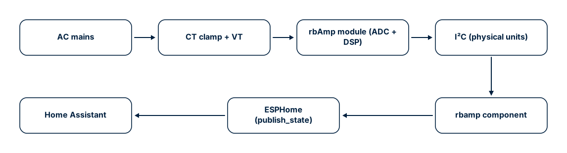
The key value proposition: physical units come ready from the module. There is no ADC on the ESP32 side, no DSP, no calibration tables, no RMS/power math. The ESPHome component is a thin I²C client + Wh integrator + HA publish layer. No lambda: math is required for basic operation.
rbAmp in the ESPHome ecosystem
If you have already used the built-in energy meters (pzemac on UART, atm90e32 on SPI, cse7766 on UART), the structure here is the same. The rbamp component is a "good citizen" of ESPHome: it uses the standard i2c: transport, the standard sensor.platform: rbamp syntax, the standard sensor slots with device_class / state_class / unit_of_measurement, and supports the full standard set of sensor filters and properties.
Compare the anatomy (identical mental model):
# ATM90E32 (SPI meter):
spi:
  clk_pin: GPIO18
  miso_pin: GPIO19
  mosi_pin: GPIO23
sensor:
  - platform: atm90e32
    cs_pin: GPIO5
    voltage_a:
      name: "Mains Voltage"
    power_a:
      name: "Mains Power"
# rbAmp (I²C meter):
i2c:
  sda: GPIO21
  scl: GPIO22
  frequency: 50kHz
rbamp:
  id: meter1
  address: 0x50
sensor:
  - platform: rbamp
    rbamp_id: meter1
    voltage:
      name: "Mains Voltage"
    power:
      name: "Mains Power"
The differences are only in the transport (i2c: instead of spi:) and in the fact that rbamp: is declared as a separate block (an id: + address: is needed for a multi-module bus). Beyond that it is plain ESPHome: the slot names (voltage, current, power, energy, frequency, power_factor) are familiar, and customization (name, update_interval, accuracy_decimals, filters:) works as usual. A detailed customization example is in Examples §1.1 "UI1 with customization — all standard ESPHome knobs".
What you measure
| Quantity | YAML slot | Range | Typical accuracy |
|---|---|---|---|
| RMS voltage | voltage |
0..300 V | ±0.5% |
| RMS current (per channel) | current / current_1 / current_2 |
0..50 A (per CT preset) | ±0.5..1% (module) |
| Active power (signed) | power / power_1 / power_2 |
±11.5 kW | ±1% |
| Power factor (signed) | power_factor / power_factor_1 / power_factor_2 |
−1..+1 | ±0.01 at PF ≈ 1 (resistive load) |
| Reactive power | reactive_power / reactive_power_1 / reactive_power_2 |
as for P | — |
| Apparent power | apparent_power (CH0 only; for CH1/CH2 — a template sensor in HA, see DIY Integrations §6) |
as for P | ±2% |
| Mains frequency | frequency |
45..65 Hz | ±0.5 Hz |
| Accumulated energy (Wh) | energy / energy_1 / energy_2 |
64-bit | depends on P accuracy |
The current and power figures are the module's own accuracy. Your total accuracy is the module plus the CT sensor you fit: a standard SCT-013 clamp adds roughly 1–3% (tightening to ±0.5–1% after a one-point calibration), a precision through-core CT about 0.3–1%. The board ships without a sensor — you pick the CT for the accuracy you need.
All instantaneous values are updated by the module autonomously with a step of ~200 ms. Wh accumulation is performed by the ESP32 based on the average power returned by the module over the interval between two update() calls. The ESPHome component hides the latch/snapshot protocol — the user only sees ready sensor entities in Home Assistant.
What the ESPHome component adds
- Ready HA sensors — every slot already has
device_class,state_class, and units configured. Theenergysensor appears in the Energy dashboard immediately without manual configuration. - NVS persistence of Wh — the total energy is written to the ESP32 flash every 5 minutes and restored before the first
publish_state. Home Assistant never sees a momentary zero after a reboot and does not interpret it as a counter reset. - Declarative sensor configuration — two YAML lines (
sensor_class:+ct_models:for UI3 orct_model:for UI1) fix the family and CT model for each channel. Factory coefficients are loaded by the module automatically — no calibration steps in the boot sequence. - Polling schedule through
PollingComponent::update()with a configurableupdate_interval(60 s by default). - Decoupled RT-read and LATCH cadences (v1.4+) — the optional
latch_interval:key lets the LATCH → snapshot → Wh integration cycle run at its own cadence whileupdate_interval:continues to control how often the ESPHome component reads the real-time V/I/P/PF/Q block. Typical use:update_interval: 3s+latch_interval: 60s— fresh dashboard values every 3 s, LATCH bus load only once a minute. Wh accuracy is preserved regardless of the ratio (master-side integration uses actual wall-clock dt between LATCH events). - NACK resilience — a three-layer discipline (SPEC §B.5) is implemented: 50 kHz by default, per-byte retry, sanity filter on NaN/Inf. Details below.
- One-shot address provisioning — the
new_address:key changes the module's I²C address in one boot cycle. Convenient for bulk-configuring a batch of devices. - Multi-module bus —
MULTI_CONF = Truelets you declare severalrbamp:blocks on a single ESP32 and poll them all in turn.
Architecture
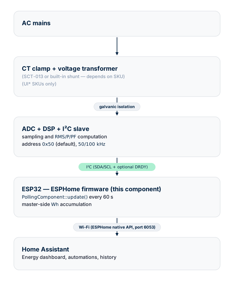
The measurement engine lives in the module; the ESP32 acts as a bridge to HA and an energy integrator. Wh is counted on the ESP32, not in the module — this matters for multi-module installations: the master's clock is more stable than the module's low-frequency oscillator, and accumulation across all modules remains consistent.
Data flow during one update()
Every update() call runs two parallel branches:
Branch 1 — instantaneous values (RT block)
- Check the status register. If the module is busy (boot, flash-write blackout) — skip without writing.
- For every declared RT sensor — read a float32 from the corresponding register.
std::isfinite()sanity filter — discards NaN/Inf, which can occur due to tearing when reading non-atomic registers.sensor->publish_state(val).
The module's bus does not support auto-increment, so the component reads each of the 4 bytes of a float32 as a separate transaction with its own address phase. This is consistent with the convention in SPEC §6, which all client libraries in the family follow.
Branch 2 — period metering (energy accumulation)
- Capture
t_latch = millis(). - Send the latch command — it closes the current accumulation period and immediately opens the next one. A single transaction closes and opens; no sample is lost at the boundary.
- After 50 ms (non-blocking timeout) — read the valid flag. If the module did not have time to integrate (polling faster than the integration period or a stale snapshot) — skip; the next cycle will catch the missed interval.
- Read the average active power for the period for every channel.
E_Wh[ch] += avg_p_W[ch] × (t_latch − last_latch_ms_) / 3_600_000.- Update
last_latch_ms_only after success on every channel. - Save to NVS if more than 5 minutes have elapsed since the last save.
The first latch after boot resets the module's accumulator and calibrates the master's clock; its result is discarded via the primed_ flag.
NVS energy persistence
Accumulated values are stored in the RbAmpPrefData structure (per-channel total + per-channel export):
struct RbAmpPrefData {
  double energy_total_wh[3];
  double energy_export_wh[3];
} __attribute__((packed));
The NVS key is derived from the component ID XORed with RBAMP_PREF_VERSION (0x52424D31 = "RBM1"). If the structure ever changes — bumping the version constant will silently discard stale data instead of misinterpreting it.
At boot setup() restores the totals before the first update(). If the component first published 0 Wh and then jumped to the saved value, Home Assistant would interpret the jump as a counter reset and start a new history segment. Restoration before the first publish prevents this.
The save frequency is determined by two conditions:
- By time — every 5 minutes (
SAVE_INTERVAL_MS = 300000). - By event — after every successful full integration cycle (all channels read without NACK).
The worst case of data loss on a sudden power outage is 5 minutes of accumulated energy. At an average load of 60 W that is 5 Wh — below the resolution of the daily bar in the Energy dashboard.
NVS wear — can the flash "wear out"?
Every save writes ~16 bytes into the ESP32 NVS section. The ESP-IDF NVS layer groups small writes into a single block and erases a page (4 KB) only when the block is full. On a 5-minute cycle:
| Metric | Value |
|---|---|
| Saves per day | 288 |
| Saves per year | ~105,120 |
| Record size | ~16 bytes |
| NVS page size | 4,096 bytes |
| Page-erase per year | ~411 (≈ 105,120 × 16 ÷ 4,096) |
| Erase cycle limit (ESP32 NOR flash datasheet) | 100,000 cycles |
| Time-to-fail (TTF) | ~240 years per single NVS page |
ESP-IDF NVS additionally performs wear-leveling across the available NVS pages (the default partition has 4 pages), which multiplies TTF by ~4×. Practical takeaway: NVS wear on the 5-minute save cycle is not a limiting factor — the hardware will become obsolete first.
When you might want to reduce the frequency: if a user forces
SAVE_INTERVAL_MS below the default (for example 30 s) through their
own custom code — recompute TTF with the same formula. The safe lower
bound for 10-year operation is ~30 s.
SPEC §B.5 discipline
ESP32 boards using the ESP-IDF v5 i2c_master driver (which is what ESPHome, arduino-esp32 v3.x, and MicroPython on ESP32 run on) periodically NACK reads from the module at 100 kHz — roughly 20% of transactions. The same DUT, the same module, but with an STM32 F103 or a Raspberry Pi as master — 0% NACK. That is, the issue is on the master side, not the module. Details are in SPEC Appendix B.5.
There is a second complication: when i2c_master_transmit_receive() returns ESP_FAIL because of a NACK, the IDF v5 driver does not zero out the user buffer. Data from the previous transaction remains. Some of these stale patterns look like plausible floats (for example 0x3C 0x2F 0xFB 0x3F → 1.962 V) and pass a naive isfinite() check.
The component implements three mitigation layers:
| Layer | Implementation | Effect |
|---|---|---|
| 50 kHz bus by default | frequency: 50kHz in the i2c: YAML block |
Reduces NACK rate ~5× empirically |
| Per-byte retry | 3 attempts, 5 ms pause, on every byte of every float32 | Removes transient NACKs before the data is used |
| Soft sanity filter | std::isfinite() without hard physical bounds |
Catches NaN/Inf/denormals from the stale buffer; allows correct edge-case values (brownout, disconnect) |
With all three layers active the component achieves > 99% valid reads on bench. The module's I²C recovery window was hardened in firmware v1.1 and v1.3, but at 100 kHz the ESP-IDF i2c_master driver-timing interaction still raises the NACK rate too high for reliable operation, so 50 kHz is the standing recommendation on ESP-IDF-based masters (ESPHome / MicroPython-ESP32 / Arduino-ESP32 all share that driver). Non-ESP32 masters (STM32, RP2040, Linux SBC) run this module at 100 kHz.
The rbAmp library family
This component is one member of the cross-platform rbAmp client library family. They all implement the same wire protocol (libs/spec/SPEC.md).
| Platform | Path in the monorepo | State |
|---|---|---|
| ESPHome (this component) | tools/esphome-rbamp/ |
Stable, HA sensors verified |
| Arduino / arduino-esp32 | libs/arduino/RbAmp/ |
Stable |
| ESP-IDF | libs/esp_idf/components/rbamp/ |
Stable, v1.2 parity |
| Python (CPython + MicroPython) | libs/python/rbamp/ |
Stable, v1.2 parity |
| STM32 HAL | libs/stm32_hal/ |
In development |
The paths show the location in the monorepo. Distribution repositories for standalone installation through Library Manager / pip /
idf_component_managerare being prepared for publication — the corresponding URLs will appear in Changelog after release.
All libraries use the same single-byte-per-transaction read convention (SPEC §6), the same period-metering state machine (SPEC §7), the same SKU variant detection algorithm (SPEC §8), the same error codes (SPEC §5). Code from any of these platforms ports to another by mechanical translation of syntax — the protocol logic is identical.
Supported SKUs
| Variant | Voltage channel | Current channels | Power | Available ESPHome slots |
|---|---|---|---|---|
| UI1 | yes | 1 | yes | voltage, current, power, energy, frequency, power_factor, reactive_power, apparent_power |
| UI2 | yes | 2 | yes | + current_1, power_1, energy_1, power_factor_1, reactive_power_1 |
| UI3 | yes | 3 | yes | + current_2, power_2, energy_2, power_factor_2, reactive_power_2 |
| I1 | no | 1 | no | current, frequency |
| I2 | no | 2 | no | + current_1 |
| I3 | no | 3 | no | + current_2 |
On I-only variants the slots power, energy, and power_factor require a declared voltage slot (checked by the schema validator) — declare them only on UI* SKUs.
What next
- Module Tiers — BASIC / STANDARD / PRO lineups and which YAML keys are available on each
- Sensor Selection — choosing a CT clamp and behavior of the
ct_model:/ct_models:keys - Wiring — GPIO pinout, pull-ups, multi-module bus
Source & issues: rb-amp/rbamp-esphome · this page in the repo: docs/01_overview.md