Overview
📦 GitHub:
rb-amp/rbamp-python— source, examples, changelog (v1.5.0).
Install:pip install rbamp
What rbAmp is
rbAmp is a compact hardware module for precision measurement of AC mains parameters over the I²C interface. It is built on a Cortex M0+ microcontroller with an integrated isolated analog front-end and factory calibration stored in flash.
From an integrator's point of view, the module behaves like a
standard I²C slave: create RbAmp(bus, 0x50), call dev.begin(),
and read the resulting values through properties and methods. The
exact same source runs on MicroPython (with machine.I2C) and
CPython (with smbus2) — the backend is selected automatically
from the type of the bus object.
What rbAmp measures
| Quantity | Python type | Range |
|---|---|---|
| RMS voltage U_rms | float, V |
0…300 V |
| Peak voltage U_peak | float, V |
0…450 V |
| RMS current I_rms | float, A |
depends on the selected sensor — see 03_sensor_selection.md |
| Peak current I_peak | float, A |
depends on the selected sensor |
| Active power P (signed in RT) | float, W |
depends on the selected sensor |
| Power factor PF | float |
−1…+1 |
| Mains frequency | int, Hz |
45…65 Hz |
| Period-averaged P | float, W |
same as P |
The RT value of active power
Pis always signed on every module tier (negative means export to the grid). The behavior of the period-averaged value (snap.avg_p[ch]inRbAmpPeriodSnapshot) depends on the module tier — see the "Module tiers" section below and 02_tiers.md.
Wiring
The module connects to the host with four wires on the LV side. The mains side is already routed inside the enclosure and is galvanically isolated.
| Wire | Purpose |
|---|---|
VCC |
+5 V (4.5..5.5 V), ~15 mA, peak ~25 mA |
GND |
shared with the host (mandatory) |
SDA, SCL |
I²C, 3.3 V logic, 5 V tolerant. Built-in 4.7 kΩ pull-ups |
DRDY |
optional, open-drain LOW for ~10 µs every ~200 ms |
The default address is 0x50 (7-bit, configurable in the range
0x08..0x77). The recommended speed for MicroPython on ESP32 is
50 kHz (SPEC §B.5); for CPython through the kernel I²C driver it
is usually 100 kHz (the NACK pattern does not surface through the
Linux kernel API).
The full rules (bus length, pull-up recommendations for a multi-module bus, wiring diagrams for RPi / ESP32 / RP2040 / STM32) are in chapter 04 · Wiring.
Module tiers (quick cheat sheet)
The current firmware (v1.2) implements only the BASIC tier — one-directional (consumption-only) metering following the logic of a classic mechanical meter:
| Tier | RT power dev.power[ch] |
Per-period accumulator snap.avg_p[ch] |
Wh counter in the package |
|---|---|---|---|
| BASIC | signed (negative = export to the grid, visible in real time) | every 200 ms window of average P is clamped to max(P, 0) before being added to the period accumulator |
monotonic — consumption only |
| STANDARD | planned for v1.3+ | planned — separate export accumulator | planned — bidirectional metering |
| PRO | planned for v1.3+ | planned + diagnostics | planned + additional counters |
For details, see chapter 02 · Module tiers. At the
package level the same RbAmp class is used regardless of tier; the
differences show up in the values the module returns.
Bidirectional metering on BASIC:
dev.energy.wh(ch)on the BASIC tier reports consumption only. If you need to account for export separately, sample the RT powerdev.power[0](ordev.read_power(0)) at about 5 Hz and split the positive and negative samples into two accumulator variables yourself. For an example, see 06_examples.md, the scenario "Bidirectional metering on the master side".
What this package does
Its main job is to hide the protocol exchange and to relieve user
code of the chores of working with registers, byte order, and the
settle times required after commands. In addition, the package
computes energy (Wh) — the module returns only the period-averaged
power, and the master does the integration using time.monotonic() /
time.ticks_us().
Without the package (direct register access via smbus2)
import struct
from smbus2 import SMBus, i2c_msg
# Read U_RMS — assemble 4 bytes over 4 transactions (SPEC §6 — no auto-increment).
buf = bytearray(4)
with SMBus(1) as bus:
    for i in range(4):
        bus.write_byte(0x50, 0x86 + i)
        buf[i] = bus.read_byte(0x50)
u_rms = struct.unpack("<f", bytes(buf))[0]
With the package
from smbus2 import SMBus
from rbamp import RbAmp
with SMBus(1) as bus, RbAmp(bus, 0x50) as dev:
    dev.begin()
    u_rms = dev.voltage          # property (one call = one transaction)
    # or: u_rms = dev.read_voltage()
Reading a period — without the package
import time, struct
with SMBus(1) as bus:
    # Latch + 50 ms settle + ready-flag check + assemble 4 bytes of avg_p
    bus.write_byte_data(0x50, 0x01, 0x27)   # REG_COMMAND, CMD_LATCH_PERIOD
    t_latch = time.monotonic()
    time.sleep(0.050)                        # settle
    bus.write_byte(0x50, 0x07)
    if bus.read_byte(0x50) & 0x01 == 0:
        # snapshot is stale — t_latch STILL has to be recorded,
        # otherwise the next snapshot would tally Wh over two periods
        return
    # ...read 4 bytes of avg_p, struct.unpack, integrate Wh:
    #   dt_s = time.monotonic() - t_prev_latch
    #   E_Wh += avg_p * dt_s / 3600
Reading a period — with the package
with SMBus(1) as bus, RbAmp(bus, 0x50) as dev:
    dev.begin()
    snap = dev.read_period_snapshot()        # latch + settle + valid + read + Wh tick
    print(snap.avg_p[0], "W")
    print(dev.energy.wh(0), "Wh")
Internally, the package guarantees:
- A 50 ms settle after
CMD_LATCH_PERIOD, and correct reading of the snapshot. - A check of the
validflag before reading; on a stale snapshot it raisesRbAmpStaleError. - Recording of the timestamp by the master's clock even on a stale snapshot (protecting against double-counting Wh on the next period).
- Per-channel Wh accumulation in double precision (CPython — 64-bit
float; MicroPython — depends on the build, see 04 · Wiring). - Automatic loading of the calibration coefficients when the current
sensor is selected via
dev.set_sensor_class(cls)+dev.set_ct_model(code)— the user does not need to know about the internal calibration registers.
When to use the package, when to access the bus directly
| Task | Package | Direct access via smbus2 / machine.I2C |
|---|---|---|
| Reading U / I / P / PF / frequency | ✅ | only for debugging on a logic analyzer |
| Per-period energy metering | ✅ | only if Wh is stored outside the package (for example, in a DB on the master side) |
| Several modules on one bus | ✅ (via sequential LATCH + a shared settle) | — |
| Bidirectional metering on BASIC | ✅ (via RT sampling — see 06_examples.md) | alternative — your own RT-read loop |
| Async streaming via asyncio / uasyncio | ✅ (async for snap in dev.stream_period()) |
hard — there is no built-in async wrapper |
| Porting to another platform | n/a | ✅ — see rbamp-spec |
The package covers every typical task in the first rows.
Architecture
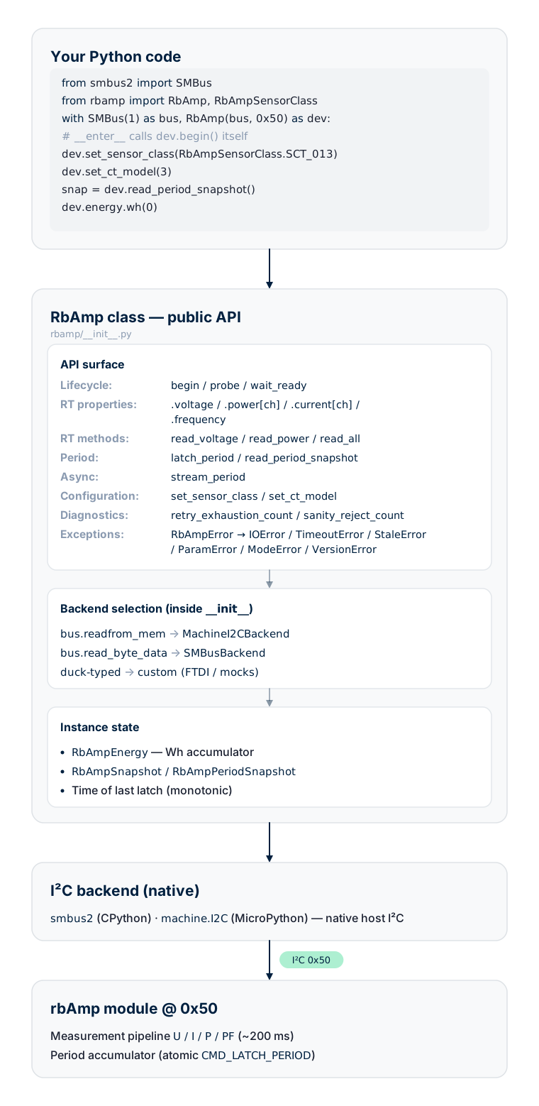
Exception hierarchy
Unlike the Arduino library (where errors are reported via
lastError() + a return code) and the ESP-IDF component (where they
are reported via esp_err_t), the Python package uses the
classic Python pattern — an exception hierarchy.
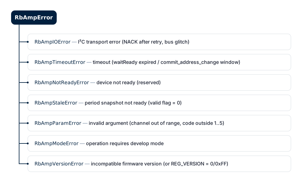
The standard Python pattern:
from rbamp import RbAmp, RbAmpStaleError, RbAmpError
try:
    snap = dev.read_period_snapshot()
except RbAmpStaleError:
    # Snapshot is stale — the master timestamp is already recorded by the package
    continue
except RbAmpError as e:
    log.warning("rbAmp failure: %s", e)
Interaction diagrams
The dev.begin() flow
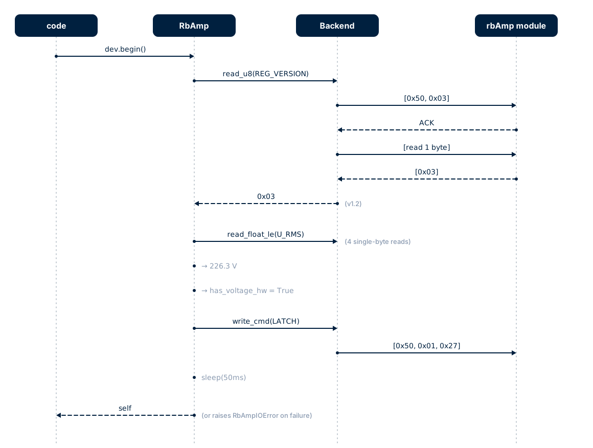
The first latch is a primer (the module returns whatever has accumulated since power-on, which is unsuitable for tariff metering). The package itself takes care of discarding this snapshot — user code never sees it.
The dev.read_period_snapshot() flow
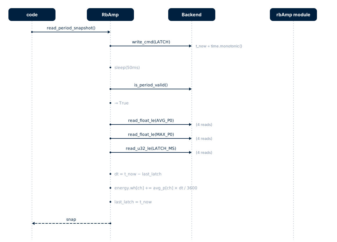
The atomic latch on the module side guarantees that every ADC micro-sample in a period lands in exactly one snapshot — no duplication and no losses at the period boundaries.
Mapping to the direct register API
A table for those migrating from their own direct-access code:
Direct API (smbus2 / machine.I2C) |
Equivalent via the package |
|---|---|
Manual 4-byte read + struct.unpack |
dev.voltage (property) or dev.read_voltage() |
Per-channel read_byte × 4 |
dev.power[ch] (_ChannelProxy) or dev.read_power(ch) |
write_byte_data(0x50, 0x01, 0x27); time.sleep(0.05) |
dev.latch_period(); time.sleep(0.05) (or directly dev.read_period_snapshot()) |
Check read_byte(0x07) & 1 |
dev.is_period_valid() or the snap.valid field |
Manual formula E_Wh += avg_p × dt / 3600 |
dev.energy.wh(0) — updated automatically |
| Manual current-sensor configuration through the direct register API | dev.set_sensor_class(cls) + dev.set_ct_model(code) — factory presets are loaded automatically |
What's next
- 02 · Module tiers — which tier for which task
- 04 · Wiring — pull-ups, bus length, per-host wiring (RPi / ESP32 / RP2040 / STM32)
- 05 · Quickstart — the first working script for both backends
- 06 · Examples — walkthrough of ready-made scenarios
- 09 · API reference — every public class + method + property + exception
- 10 · Troubleshooting — when something doesn't work
Source & issues: rb-amp/rbamp-python · this page in the repo: docs/01_overview.md