04 · Period Metering and Tariff Accounting
For tariff energy accounting (Wh per 1 min / 15 min / 1 hour / day / month / year) rbAmp provides an atomic period latch mechanism: a single I2C command freezes the time-averaged power over a period, and the master multiplies it by its own wall-clock dt to get Wh.
This is the production-grade way to extract energy data. The alternative — integrating RT P_real on the master side every 200 ms — yields the same result on BASIC, but keeps the master continuously active.
Why energy uses a latched snapshot, not chip-side Wh
A single time base, owned by the master
In a multi-module system the time base must live on the master. The chip therefore does not integrate Wh internally. Instead:
- The chip exposes a time-independent statistic — the average P over the period.
- The master multiplies it by its own wall-clock dt.
- All modules share the same time reference → no drift accumulates in the system-wide energy total.
The formula
E_Wh = avg_P_W × master_dt_seconds / 3600Where:
avg_P_W— the value ofPERIOD_AVG_P_W, read afterCMD_LATCH_PERIOD.master_dt_seconds— the seconds elapsed between two successive latches, measured by the master.
Atomic period latch — concept
What the command does
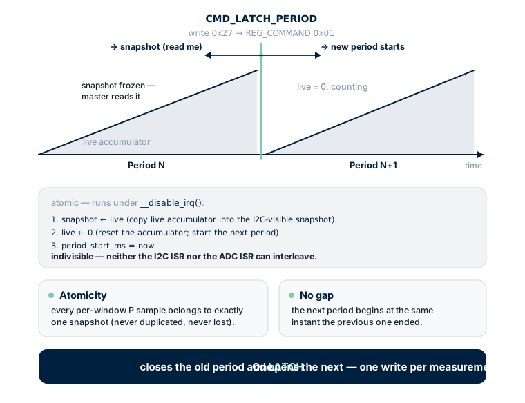
Writing 0x27 to REG_COMMAND = 0x01 triggers an atomic sequence inside the firmware (executed under __disable_irq()):
1. snapshot ← live      (copy the live accumulator into the I2C-visible snapshot)
2. live     ← 0         (reset the accumulator; start the next period)
3. period_start_ms = now
These three steps are indivisible — neither the I2C ISR nor the ADC ISR can interleave between them. This guarantees:
- Atomicity: every per-window P sample belongs to exactly one snapshot — either the previous one or the next one — never duplicated, never lost.
- No gap: the new period begins at the same instant the previous one ended — there is no blind interval.
Where the snapshot lives
After a latch, the period-snapshot registers (0xBE..0xCD, plus 0xDC..0xDF for ch0 avg_p, plus 0xE0..0xE3 for MAX_P, plus 0xEC..0xEF for the diagnostic PERIOD_LATCH_MS) return the just-closed period. Note that this range is not contiguous — 0xD0..0xDB holds the Q block (live RT, not period snapshot) and 0xE4..0xEB is reserved/factory. See chapter 11 §4.11–4.13 for the exact layout. The live accumulator already starts counting the next period; those snapshot registers update only on the next latch.
One write — closes and opens
This is the defining property of the rbAmp latch. A single LATCH command simultaneously:
- Closes the period that just ended (its data → snapshot)
- Opens the next period (live ← 0)
The master needs one write per measurement, not two (as in a naive "start → stop → read" implementation).
Continuous polling cycle (recommended)
master                          chip
------                          ----
                                accumulator running since boot...
write CMD_LATCH (0x27)   ────►  snapshot ← live (since-boot — DISCARD)
                                live ← 0, period_start = T0
t0 = master.clock()      ◄──── first latch — primer (discard)
  [wait 60 seconds]
write CMD_LATCH          ────►  snapshot ← live (over [T0..T1] — KEEP)
                                live ← 0, period_start = T1
t1 = master.clock()
read avg_p_W @ 0xDC      ────►  float32 LE
E1_Wh = avg_p × (t1 − t0) / 3600
  [wait 60 seconds]
write CMD_LATCH          ────►  snapshot ← live (over [T1..T2] — KEEP)
                                live ← 0, period_start = T2
t2 = master.clock()
read avg_p_W
E2_Wh = avg_p × (t2 − t1) / 3600
...and so on. t1 is both the end of period 1 and the start of period 2.
The first latch is a primer (discard)
The first latch after boot captures whatever the accumulator collected from power-on until the master's first call — an undefined-length window unsuitable for billing. Discard its result. From the second latch onward, data is clean and usable.
Period snapshot registers
| Address | Name | Type | When to read | Description |
|---|---|---|---|---|
0x07 |
PERIOD_VALID |
u8 | read first | bit0 = 1 if snapshot is fresh and valid, 0 if stale (race or premature latch) |
0xDC..0xDF |
PERIOD_AVG_P_W[0] |
float32 LE | primary | PRODUCTION — mean P_real of channel I0 over the period (W) |
0xC2..0xC5 |
PERIOD_AVG_P_W[1] |
float32 LE | UI2/UI3 | Mean P_real of channel I1 |
0xC6..0xC9 |
PERIOD_AVG_P_W[2] |
float32 LE | UI3 | Mean P_real of channel I2 |
0xE0..0xE3 |
PERIOD_MAX_P_W |
float32 LE | optional | Peak P_real during the period (for demand tariffs) |
0xEC..0xEF |
PERIOD_LATCH_MS |
u32 LE | diagnostic | Chip's view of dt between latches (compare with master dt) |
0xBE..0xC1 |
PERIOD_COMMIT_COUNT |
u32 LE | diagnostic | Number of RT windows that landed in this period |
STANDARD / PRO additions for bidirectional accounting
| Address | Name | Type | Description |
|---|---|---|---|
PERIOD_AVG_P_NEG_W[0] |
float32 LE | Mean export power for channel I0 over the period (W, ≥ 0 in magnitude) — STANDARD/PRO only | |
PERIOD_AVG_P_NEG_W[1..2] |
float32 LE | Same for channels I1, I2 — STANDARD/PRO only |
The numeric addresses of
PERIOD_AVG_P_NEG_W[0..2]are documented in the SKU datasheet of the STANDARD/PRO product (no canonical placeholder is used in this chapter — the addresses are tier-specific). On BASIC modules these registers do not exist; reads from an unmapped address return0x00(firmware never NACKs on reads — see chapter 11 §5.2). Master code that targets all tiers should detect "no bidirectional support" by readingSTATUS/PRODUCT_ID/FW_TIERand fall back to RT-based accounting (see 10_arduino_examples.md → Example 5).
Master-side algorithm
Basic cycle (one module, 60-second period)
#include <Wire.h>
#define RB_ADDR 0x50
void setup() {
  Serial.begin(115200);
  Wire.begin();
  delay(300);
  // 1. Primer latch (discard result)
  rb_write_u8(RB_ADDR, 0x01, 0x27);
}
void loop() {
  static uint32_t t_prev = millis();
  delay(60000);                                    // wait 60 seconds
  // 2. Final latch — closes [t_prev, now]
  rb_write_u8(RB_ADDR, 0x01, 0x27);
  uint32_t t_now = millis();
  delay(50);                                       // firmware finishes in ~5 ms; allow margin
  // 3. Check PERIOD_VALID
  uint8_t valid = rb_read_u8(RB_ADDR, 0x07);
  if ((valid & 0x01) == 0) {
    // Race or premature latch — retry
    delay(250);
    rb_write_u8(RB_ADDR, 0x01, 0x27);
    t_now = millis();
    delay(50);
    valid = rb_read_u8(RB_ADDR, 0x07);
    if ((valid & 0x01) == 0) {
      Serial.println("WARN: two stale latches in a row");
      t_prev = millis();
      return;
    }
  }
  // 4. Read the snapshot
  float avg_p = rb_read_float_le(RB_ADDR, 0xDC);
  float max_p = rb_read_float_le(RB_ADDR, 0xE0);
  // 5. Compute energy on master clock
  float dt_s = (t_now - t_prev) / 1000.0f;
  float e_wh = avg_p * dt_s / 3600.0f;
  Serial.printf("[+%5.1fs] E=%.3f Wh  avg_P=%.1f W  max_P=%.1f W\n",
                dt_s, e_wh, avg_p, max_p);
  t_prev = t_now;
}
What is essential in this code
- First latch is a primer — its result is discarded.
PERIOD_VALIDis read BEFORE using the snapshot — otherwise stale data can leak through on a race.- dt is measured on the master, not derived from
PERIOD_LATCH_MS— the chip register is only for drift diagnostics. t_prevupdates to the t_now of a successful latch, not to the original period start — this keeps the chain seamless without gaps.
Bidirectional accounting (STANDARD / PRO)
This section applies to STANDARD and PRO product tiers only. On a BASIC module the
PERIOD_AVG_P_NEG_Wregisters are not allocated (reads return0x00), andPERIOD_AVG_P_Wis always ≥ 0 (negative samples are dropped from the accumulator).
What bidirectional accounting means
The chip integrates two separate accumulators per period:
- Consumption: integral of
max(P, 0) × dt— positive power only. - Export: integral of
max(−P, 0) × dt— negative power only, by magnitude.
The sum of both gives the total energy that passed through the meter in absolute terms; the difference is the net consumption (what a mechanical disc meter would show).
Applications
- Homes with solar panels: consumption and export are billed under different tariffs (feed-in tariff)
- Systems with battery storage: tracking charge/discharge cycles
- Wind turbines, regenerative loads, V2G EV chargers
Registers (STANDARD / PRO)
| Address | Name | Description |
|---|---|---|
0xDC |
PERIOD_AVG_P_W[0] |
Mean consumption P (≥ 0), as on BASIC |
| (SKU-specific) | PERIOD_AVG_P_NEG_W[0] |
Mean export P (≥ 0 in magnitude) |
Algorithm for STANDARD / PRO
// Bidirectional accounting, 60-second period
#define REG_PERIOD_AVG_P_NEG 0xFE   // placeholder sentinel — replace with the actual address from your SKU datasheet. DO NOT use 0xD0 — that address is allocated to the Q (reactive power) register block on production firmware.
void loop() {
  static uint32_t t_prev = millis();
  delay(60000);
  rb_write_u8(RB_ADDR, 0x01, 0x27);
  uint32_t t_now = millis();
  delay(50);
  if ((rb_read_u8(RB_ADDR, 0x07) & 0x01) == 0) {
    t_prev = millis();
    return;
  }
  float avg_p_consume = rb_read_float_le(RB_ADDR, 0xDC);                  // ≥ 0
  float avg_p_export  = rb_read_float_le(RB_ADDR, REG_PERIOD_AVG_P_NEG);  // ≥ 0
  float dt_s = (t_now - t_prev) / 1000.0f;
  float e_consume_wh = avg_p_consume * dt_s / 3600.0f;
  float e_export_wh  = avg_p_export  * dt_s / 3600.0f;
  float e_net_wh     = e_consume_wh - e_export_wh;
  Serial.printf("[%.1fs] consume=%.3f Wh  export=%.3f Wh  net=%+.3f Wh\n",
                dt_s, e_consume_wh, e_export_wh, e_net_wh);
  t_prev = t_now;
}
What is not available on BASIC
If you own a BASIC-tier module and need bidirectional accounting, you have two options:
- Master-side integration — read RT
P_real(0xA6) every ~200 ms and integrate positive and negative samples separately on the master side. See Example 5 in 10_arduino_examples.md. Accuracy is slightly lower (due to sampling discretisation), but works on any firmware. - Upgrade the hardware to a STANDARD or PRO product tier. Contact your supplier — bidirectional support is a hardware + firmware combination, not a firmware-only flag.
I-only variants — period metering returns zero
On I1/I2/I3 (and higher I*-only variants) without a voltage sensor:
PERIOD_AVG_P_W[*]is always 0.0f — no U means there is nothing to integrate.PERIOD_VALIDstill reports 1 (the snapshot is valid, just zero).PERIOD_MAX_P_Wis also 0.
For I-only variants the on-chip period metering does not deliver an energy reading. The master must either:
- Use its own voltage sensor and integrate
I_rms × U_master × cos(φ)_master(more complex; requires phase synchronisation), or - Use the I-only module only for current-presence monitoring, and pair it with a UI* module or an external meter for energy.
Event-driven vs periodic polling
Periodic (cron-style)
The master reads every N seconds on a timer:
// Once per hour
setInterval(60 * 60 * 1000, [](){
  rb_write_u8(0x50, 0x01, 0x27);
  // ... read snapshot, accumulate Wh
});
Suitable for classical billing (1-min, 15-min, 1-hour).
Event-driven
The master issues a latch when an external event occurs:
- A pulse from the utility's electronic meter (cross-check)
- A tariff change (peak / off-peak)
- A user query ("how much have I used so far?")
void on_tariff_change() {
  rb_write_u8(0x50, 0x01, 0x27);    // close the period under the old tariff
  delay(50);
  if (rb_read_u8(0x50, 0x07) & 0x01) {
    float avg_p = rb_read_float_le(0x50, 0xDC);
    save_period_to_tariff_a_bucket(avg_p, current_dt_s);
  }
  // the next period accumulates into bucket B
}
Restarting the period
To discard the live accumulator and start fresh, issue an extra latch and ignore its result:
void restart_period() {
  rb_write_u8(0x50, 0x01, 0x27);    // close current + start new
  // do not read the snapshot — discard
}
After this, resume a normal latch cycle from scratch.
Multi-module — simultaneous latch
If the master wants synchronous snapshots from all modules (for an instantaneous house energy balance), there are two approaches.
Approach 1 — sequential latch (simple)
The master latches each module in turn:
const uint8_t modules[] = {0x50, 0x51, 0x52};
uint32_t t_prev[] = {0, 0, 0};
void setup() {
  Wire.begin();
  // Primer
  for (int i = 0; i < 3; i++) {
    rb_write_u8(modules[i], 0x01, 0x27);
    t_prev[i] = millis();
  }
}
void loop() {
  delay(60000);
  for (int i = 0; i < 3; i++) {
    rb_write_u8(modules[i], 0x01, 0x27);
    uint32_t t_now = millis();
    delay(50);
    if (rb_read_u8(modules[i], 0x07) & 0x01) {
      float avg_p = rb_read_float_le(modules[i], 0xDC);
      float dt_s = (t_now - t_prev[i]) / 1000.0f;
      float e_wh = avg_p * dt_s / 3600.0f;
      Serial.printf("[0x%02X] E=%.3f Wh\n", modules[i], e_wh);
      t_prev[i] = t_now;
    }
  }
}Downside: latch instants differ by a few milliseconds. For a 60-second period this yields < 0.1 % error — negligible.
Approach 2 — broadcast latch via general call (precise, opt-in)
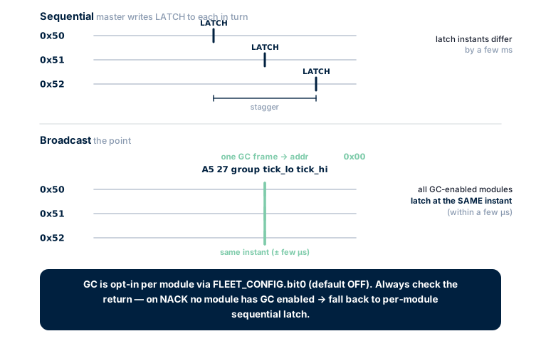
The I²C general-call address 0x00 is a packet that all slaves receive simultaneously. rbAmp accepts a canonical 5-byte frame on the general-call address that triggers CMD_LATCH_PERIOD on every module that has GC reception enabled. GC is opt-in per module via FLEET_CONFIG.bit0 (default OFF) — see 02_initialization.md for the enable sequence and frame format.
// Canonical 5-byte GC frame: A5 27 group tick_lo tick_hi.
// Returns true on ACK, false on bus-level NACK (no module has GC enabled).
bool broadcast_latch(uint16_t tick16, uint8_t group = 0) {
  Wire.beginTransmission(0x00);                // general call
  Wire.write(0xA5);                            // frame magic
  Wire.write(0x27);                            // CMD_LATCH_PERIOD opcode
  Wire.write(group);                           // group_id (0 = all-call)
  Wire.write((uint8_t)(tick16 & 0xFF));        // tick_lo
  Wire.write((uint8_t)((tick16 >> 8) & 0xFF)); // tick_hi
  return Wire.endTransmission() == 0;
}
The master keeps a 16-bit tick counter that increments on every broadcast. Each module mirrors the last accepted tick at GC_TICK (0x59), so the master can detect a missed broadcast on a specific module.
After the broadcast latch the master reads each module's snapshot by its individual address. Always check the return value — on NACK the GC frame did not land (no module has GC enabled), and the master must fall back to per-module sequential latch:
const uint8_t modules[] = {0x50, 0x51, 0x52};
uint32_t t_prev;
uint16_t gc_tick = 0;
void setup() {
  Wire.begin();
  if (!broadcast_latch(gc_tick++)) {
    // Fall back: per-module sequential latch.
    for (uint8_t m : modules) rb_write_u8(m, 0x01, 0x27);
  }
  t_prev = millis();
}
void loop() {
  delay(60000);
  if (!broadcast_latch(gc_tick++)) {
    for (uint8_t m : modules) rb_write_u8(m, 0x01, 0x27);
  }
  uint32_t t_now = millis();
  delay(50);
  float dt_s = (t_now - t_prev) / 1000.0f;
  for (int i = 0; i < 3; i++) {
    if (rb_read_u8(modules[i], 0x07) & 0x01) {
      float avg_p = rb_read_float_le(modules[i], 0xDC);
      float e_wh = avg_p * dt_s / 3600.0f;
      Serial.printf("[0x%02X] E=%.3f Wh  P_avg=%.1f W\n",
                    modules[i], e_wh, avg_p);
    }
  }
  t_prev = t_now;
}Advantage: precise synchronisation — snapshots are taken at the same instant across all GC-enabled modules, within a few microseconds.
Use case: critical for instantaneous balancing (for example house_consume − solar_export at one moment in time).
Broadcast latch is opt-in per module via
FLEET_CONFIG.bit0(default OFF on a fresh module). When OFF, the slave NACKs the general-call frame and the master falls back to per-module sequential latch automatically. See 02_initialization.md — General Call (broadcast at address 0x00) — for the enable sequence and frame format.
Choosing the period length
| Application | Recommended dt |
|---|---|
| Live UI dashboard | 1 s (or read RT P_real directly) |
| Trend chart, 1-minute resolution | 60 s |
| 15-minute peak-demand metering | 900 s |
| Hourly billing | 3600 s |
| Daily totals | Accumulate hourly latches on the master; do not let a single period exceed 1 hour |
Periods longer than 1 hour are allowed, but for very long periods the per-window accumulator can in principle overflow under extreme worst-case loads. For domestic loads ≤ 15 kW and periods ≤ 1 hour there is no overflow risk; for larger loads, prefer shorter periods.
PERIOD_MAX_P_W — peak demand
Register 0xE0 reports the maximum power observed in any RT window inside the period. Uses:
- Peak-demand tariffs: utilities bill the highest 15-minute demand of the month for capacity charges.
- Inrush detection: motor starts produce a 5–10× nominal spike —
max_P >> avg_Pflags the event. - Sanity check: if
max_Pgreatly exceedsavg_P, the load is bursty — normal for many household scenarios, but a flag worth investigating if the load is expected to be steady.
Atomicity is guaranteed
CMD_LATCH_PERIOD runs with interrupts disabled during the snapshot copy (a few microseconds). The master can never read a half-updated snapshot — even if the master reads bytes immediately after the write, the firmware finishes updating the block before the next I2C transaction completes (at least 10+ µs elapse between write and read).
The same atomicity ties the accumulator reset to the snapshot copy — every P sample is in exactly one snapshot (either the previous period or the next one), never both, never neither.
What the master must NOT do
- ❌ Do not compute
U_rms × I_rms × dt— that is apparent energy (VAh), not Wh. Apparent power includes reactive content and overcharges any inductive load. UsePERIOD_AVG_P_W. - ❌ Do not infer direction from
I_rms— RMS is always ≥ 0. Direction lives in the sign ofP_real. - ❌ Do not use
PERIOD_LATCH_MSfor Wh — that register is diagnostic and may drift with the chip clock.master_dtis authoritative. - ❌ Do not latch faster than the RT-commit cycle. The chip needs at least one mains period (~20 ms at 50 Hz) of accumulation plus settling — minimum 50 ms between
CMD_LATCH_PERIODissues. Latching faster yields an empty snapshot (PERIOD_VALID = 0). 200 ms is a safe practical floor for steady-state polling; see chapter 11 §6.0 / §6.4.
Clock-drift diagnostics
PERIOD_LATCH_MS is a diagnostic-only register — it reports dt as accumulated by the chip's SysTick, which is starved when interrupts and DMA are heavy. The cross-check should use a wide envelope:
uint32_t chip_dt = rb_read_u32(0x50, 0xEC);
uint32_t master_dt = t_now - t_prev;
float ratio = (float)chip_dt / (float)master_dt;
if (ratio < 0.70f || ratio > 1.05f) {
  Serial.printf("WARN: chip drift outside ±30%% envelope, ratio=%.3f\n", ratio);
}
Acceptance: up to 30 % undercount under load is normal (ratio as low as ~0.70). This is by design — see 05_troubleshooting.md §13. Do not use a tight 3 %–5 % threshold; it will mass-reject healthy modules.
This drift does not affect Wh accuracy (Wh uses the master clock); PERIOD_LATCH_MS is for surfacing severe chip-side anomalies only.
Next
- 05_troubleshooting.md — what to do when values look wrong
- 10_arduino_examples.md — Example 5 (master-side bidirectional on BASIC firmware)